
Horizontal high pressure planet roller mill

A planetary roller and high-pressure technology, which is applied in the field of crushing machinery, can solve the problems of uneven feeding, less extrusion times, and short residence time, and achieve the effects of prolonging service life, high crushing efficiency, and fine particle size

Inactive Publication Date: 2006-03-22
WUHAN UNIV OF SCI & TECH
View PDF1 Cites 8 Cited by
  • Summary
  • Abstract
  • Description
  • Claims
  • Application Information

AI Technical Summary

Problems solved by technology

At present, there are three main problems in the use of Raymond mills: (1) Raymond mills crush materials mainly by driving the grinding rollers to rotate when the main shaft rotates to generate centrifugal force on the grinding ring to crush materials, but due to The spindle speed of the Raymond mill is low, and the pressure of the grinding roller on the material is not enough, resulting in low production efficiency; (2) The classification accuracy is poor, and the particle size of the general product can only be controlled between 100 and 325 mesh; (3) Due to the use of a blade to give material, resulting in uneven feeding, easy to cause direct contact between the grinding roller and the grinding ring, resulting in high-frequency vibration and noise, which deteriorates the operating environment and aggravates the wear of the grinding roller and grinding ring
[0003] In addition, although "a vertical planetary spiral roller mill" (ZL03254531.2) can improve the service life, reduce energy consumption, and reduce production costs, there are still: (1) due to vertical feeding and vertical discharging, there will be A small part of the material is directly discharged without being crushed in the machine, so the particle size of the material after crushing is uneven; (2) The residence time of the material in the mill is short, and the number of extrusions is small, so it is difficult to achieve ultra-fine crushing of the material; (3) ) The mill cannot evenly distribute the material, so the spiral roller and the grinding ring will collide with each other and produce a "knocking cylinder" phenomenon, resulting in faster wear of the grinding roller and grinding ring

Method used


Image

  • Horizontal high pressure planet roller mill
  • Horizontal high pressure planet roller mill

Examples


Embodiment Construction

[0013] The specific implementation of the present invention will be further described below in conjunction with accompanying drawing:

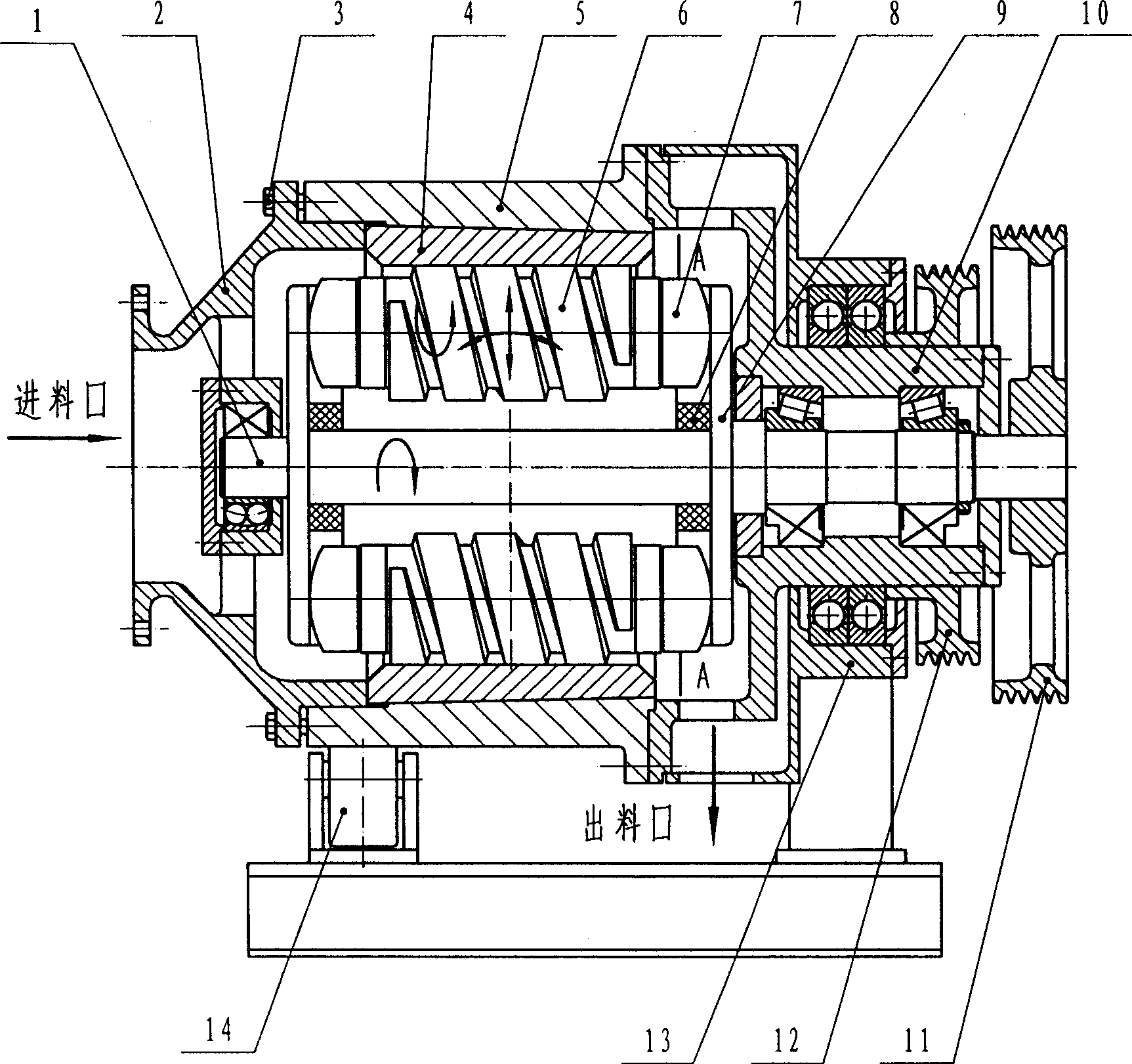
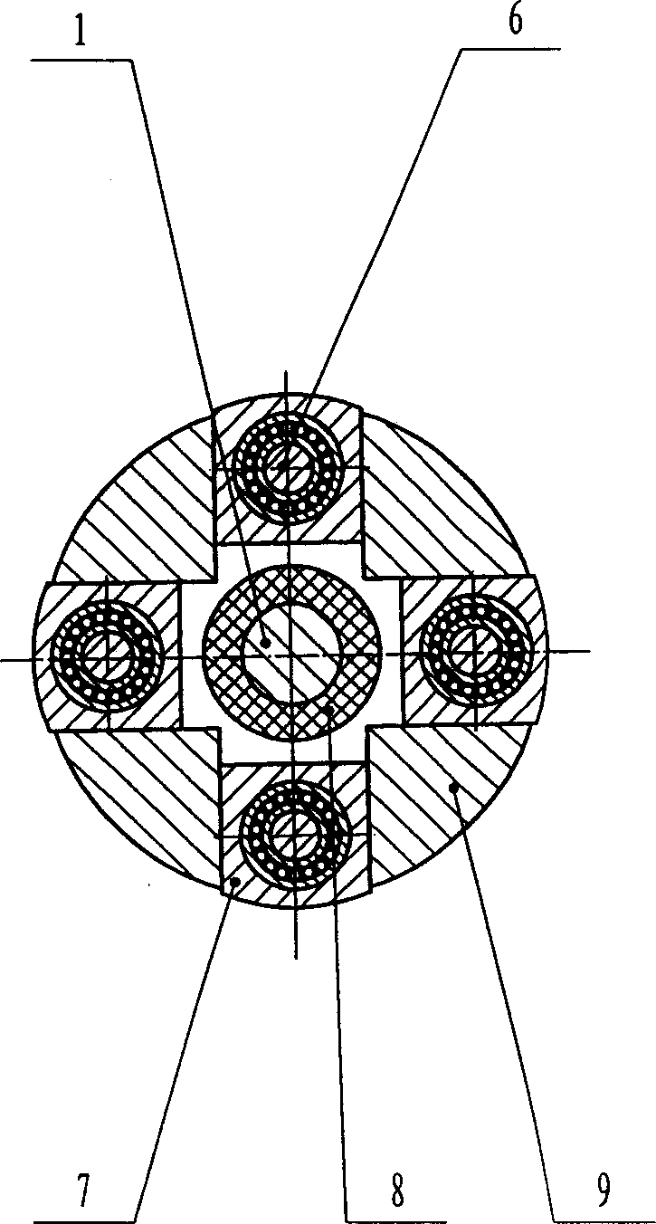
[0014] figure 1 It is a specific embodiment of the present invention. As shown in the figure, the main shaft [1] is horizontally installed in the left bearing seat [2] and the right bearing seat [10] through the bearing, and the right bearing seat [10] is installed in the frame bearing In the seat [13], a transmission wheel [12] is fixedly installed on the end of the right bearing seat [10], and a transmission wheel [11] is fixedly installed on the right end of the main shaft [1]; The bearing housings [2] and [10] are connected and supported on the idler roller [14]. The grinding ring sleeve [5] is provided with a grinding ring [4], and the grinding ring [4] is provided with a spiral roller [6]. Roller [6] is horizontally installed in two guide groove discs [9] of main shaft [1] by helical roller bearing seat [7].

[0015] Among them: the gr...


PUM


Abstract

The present invention relates to a kind of horizontal high-pressure planetary roller mill. The technological scheme is that the planetary roller mill has main shaft installed horizontally in the right and left bearing seats via bearings, right bearing seat installed inside the frame bearing seat, one driving wheel fixed to the end of the right bearing seat, the other driving wheel fixed to right end of the main shaft, mill ring jacket on the support roller, mill ring inside the mill ring jacket, horizontally installed spiral roller inside the mill ring, conic surface connection between mill ring and mill ring jacket, and screw connection between the mill ring jacket and the left bearing seat. The planetary roller mill has the features of homogeneous distribution of material, high crushing efficiency, fine granularity of the product and low power consumption.

Description

1. Technical field [0001] The invention belongs to crushing machinery. In particular, it relates to a horizontal high-pressure planetary roller mill. 2. Background technology [0002] Raymond mill is widely used crushing equipment in non-metallic mineral industry (Wu Xuefeng. Development and practice of ultra-fine Raymond mill. China Non-metallic Mineral Industry Guide, 2001.1), which has the characteristics of stable performance, wide application range and large processing capacity. At present, there are mainly the following three problems in the use of Raymond mills: (1) Raymond mills crush materials mainly by driving the grinding rollers to rotate when the main shaft rotates to generate centrifugal force on the grinding ring to crush materials, but due to The spindle speed of the Raymond mill is low, and the pressure of the grinding roller on the material is not enough, resulting in low production efficiency; (2) The classification accuracy is poor, and the particle size...

Claims


Application Information

Patent Timeline
Patent Type & Authority Applications(China)
IPC IPC(8): B02C15/08
Inventor 刘旺汪建春杨启梁严运兵张光德李欣灿孙文凯
Owner WUHAN UNIV OF SCI & TECH
Learn More