Cord lock

a technology of cord locks and screws, applied in the field of cord locks, can solve the problems of hard grip and deterioration of operability, and achieve the effects of improving operability, stably strong pinching force, and thin and compact structur

Active Publication Date: 2018-06-07
NIFCO INC
View PDF16 Cites 11 Cited by
  • Summary
  • Abstract
  • Description
  • Claims
  • Application Information

AI Technical Summary

Benefits of technology

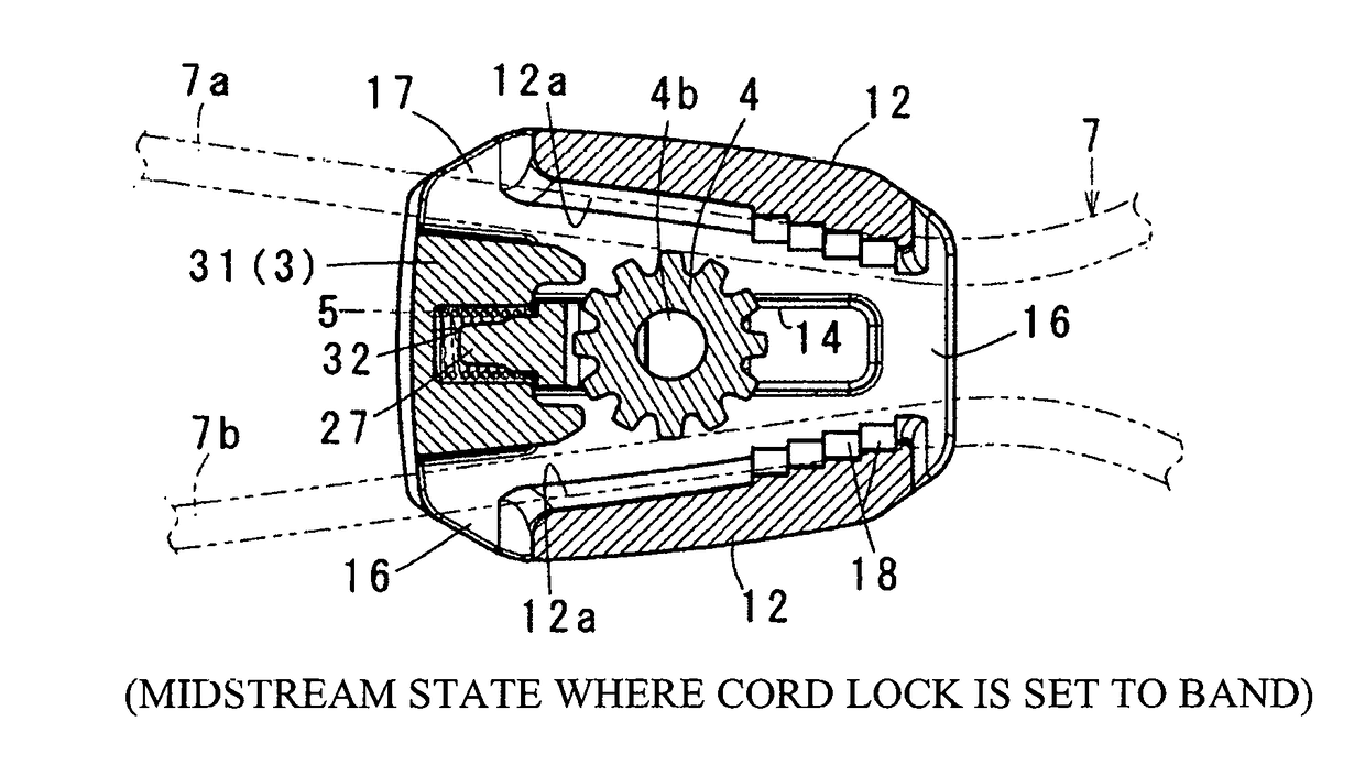
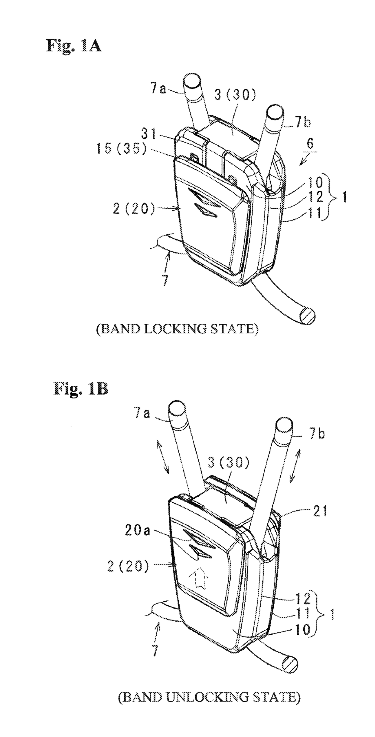
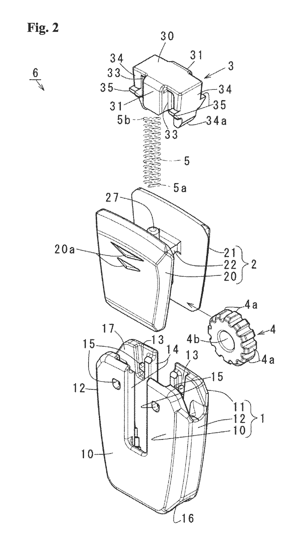
[0018]In each of the inventions according to the first and second aspects, an improved operability can be obtained by the operating portions arranged in both outer surfaces of the case front and rear walls as mentioned above in comparison with the structure in which the operating portion is provided only in one of the front and rear walls or is provided in both sides of the case, and a stably strong pinching force can be obtained by employment of the gear-shaped engagement portion. Further, in each of the inventions, since the operating portion is arranged in an axial direction of the gear-shaped engagement portion, the operating portion can be set to be wide in surface without deterioration of an outer appearance, and can be made thin and compact as a whole. Further, since the gear-shaped engagement portion is rotatably supported to the pivot portion, the gear-shaped engagement portion is hard to be worn away. In addition, the following advantages are provided.
[0019]The invention according to the first aspect is excellent in an assembling property since the gear-shaped engagement portion is easily supported to the operating button, for example, as can be estimated from the examples in FIGS. 7A to 10C, as the support structure of the gear-shaped engagement portion, and is assembled into the main body from this state. Further, since the gear-shaped engagement portion is pivotally supported to the pivot portion within the main body, it is possible to efficiently reduce or absorb a load even if the great load is applied from the band, it is possible to stably maintain the pinching force applied to the band and it is possible to improve the durability.
[0020]The invention according to the second aspect is excellent in the assembling property since the gear-shaped engagement portion is easily supported to the operating button, for example, as can be estimated from the examples in FIGS. 3A-3C, 7A-7C and 8A-8C, as the support structure of the gear-shaped engagement portion, and is assembled into the main body from this state. Further, since the gear-shaped engagement portion is pivotally supported to the pivot portion in a state of being pinched between the support piece and the corresponding portion thereto within the main body, the gear-shaped engagement portion is not accidentally inclined and does not become non-rotatable even if any great load is applied from the band. As a result, it is possible to efficiently reduce or absorb the excessive external force, it is possible to stably maintain the pinching force and it is possible to improve the durability.
[0021]In the invention according to the third aspect, the elastically deformation of the connection portion connecting the operating portions to each other is restricted in a state in which the operating button is assembled in the main body, on the basis of the state in which the front and rear walls of the main body are pinched by both the operating portions as is known from FIGS. 4A, 4B and 4C. As a result, the structure can be easily achieved without deterioration of quality and can also be thinned.
[0022]In the invention according to the fourth aspect, the elastically deformation of the support piece and the support portion provided in the connection portion in the protruding manner is restricted in the state in which the operating button is assembled in the main body, on the basis of the state in which the support piece and the support portion are pinched between the gear-shaped engagement portion and the corresponding one of the main body front and rear walls as is estimated from FIGS. 4A, 4B and 4C. As a result, the structure can be easily achieved without deterioration of quality and can also be thinned.
[0023]In the invention according to the fifth aspect, it is possible to secure an entire rigidity and improve a stamping strength under existence of the come-off prevention portion. Further, since the insertion position of the band is divided between the right and left side walls and the come-off prevention portion as shown in the embodiment, it is possible to easily prevent the band from intertwining as is estimated from FIG. 6C.

Problems solved by technology

As a result, it is hard to grip and the operability is deteriorated.

Method used


Image

  • Cord lock
  • Cord lock
  • Cord lock

Examples


modified example 1

[0055]FIGS. 7 and 8 show the other example of the elastically deforming portion 22a mentioned above in correspondence to FIGS. 3A, 3B and 3C. In this description, same reference numerals are attached to the same or similar positions to the above embodiment, and only changed points will be made apparent while omitting an overlapping description as much as possible.

[0056]An operating button 2 according to the modified example 1 has elastically deforming portions 24a and 26a obtained by reducing thickness of positions where the support piece 24 and the support portion 26 (a support piece 26A in the case of FIGS. 8A, 8B and 8C) are connected to the connection portion 22, that is, a base end, in place of the elastically deforming portion 22a according to the above embodiment. As a result, in the modified example 1, in the case where the gear-shaped engagement portion 4 is assembled in the operating button 2, the support piece 24 and the support portion 26 (the support piece 26A) displace...

modified example 2

[0059]FIGS. 9A to 9C show a modified example in which the support portion 26 and the support piece 26A mentioned above are omitted, FIG. 9A corresponds to FIG. 3A, FIG. 9B corresponds to FIG. 5B, and FIG. 9C corresponds to FIG. 6B. In this description, same reference numerals are attached to the same or similar positions to the above embodiment, and only changed points will be made apparent while omitting an overlapping description as much as possible.

[0060]An operating button 2 according to the modified example 2 is changed in a point that the support portion 26 and the support piece 26A are omitted among the support piece 24 and the support portion 26 or the support piece 26A mentioned above, a point that the gear-shaped engagement portion 4 is constrained in a freely oscillating manner in an internal space 23 divided by the support piece 24, the connection portion 22 and the rear wall 11, and a point that the support piece 24 is formed in the elastically deforming portion 24a by ...

modified example 3

[0063]FIGS. 10A to 10C show the other modified example of the pivot portion 25 mentioned above, FIG. 10A corresponds to FIG. 3A, FIG. 10B corresponds to FIG. 5B, and FIG. 10C corresponds to FIG. 6B. Also in this description, same reference numerals are also attached to the same or similar positions to the above embodiment, and only changed points will be made apparent while omitting an overlapping description as much as possible.

[0064]The operating button 2 according to the modified example 3 is changed from the structure mentioned above in a point that the support piece 24 is changed to a support portion 24A in which the pivot portion is omitted, a point that the support portion 26 and the support piece 26A are omitted, a point that a pivot portion 25A is provided in a protruding manner in an inner surface of the rear wall side operating portion 21 which is one of both the operating portions, and a point that the long hole 14 provided in the rear wall 11 is made a little longer tha...


PUM


Abstract

A cord lock includes a main body having front and rear walls and two side walls, an elongated hole, and an inclined portion formed in an inner surface of the side walls; and an operating button having front and rear wall side operating portions arranged on the front wall and the rear wall, respectively, a connecting portion integrally connected to the front and rear wall side operating portions through the elongated hole, a biasing device biasing the front and rear side operating portions to the one side opening to cooperate with the inclined portion, and a gear-shaped engagement portion adapted to pinch the band inserted into the tubular shape. The operating button has a pivot portion, wherein a distance between an axial end of the pivot portion and a shaft end supporting the gear-shaped engagement portion is narrower than a thickness of the gear-shaped engagement portion.

Description

BACKGROUND OF THE INVENTIONTechnical Field[0001]The present invention relates to a cord lock which is preferable for locking both end sides of a band (including a rope, a cord and similar structures, same applies to the below description), for example, arranged around an opening edge of a shoe and clothes with an optional length, or adjusting a drawing amount and a fastening degree of the band.Related Art[0002]FIGS. 11A and 11B show a cord lock (a band fastening tool) disclosed in JP H02-6809 Y. In this structure, the cord lock is constructed by a main body 1 which is formed into a tubular shape with front and rear walls and both side walls; a band 3 can insert from one side opening of the tubular shape into the other side opening, and the cord lock has a long hole 8 arranged so as to face to the front and rear walls and extending in a direction of the tube and an inclined portion a formed in an inner surface of both the side walls and expanding toward the depth, and an operating bu...

Claims


Application Information

Patent Timeline
Patent Type & Authority Applications(United States)
IPC IPC(8): A43C7/04F16G11/10
CPCA43C7/04F16G11/101F16G11/105A44B11/06F16G11/106
Inventor SHIMIZU, YOHEI
Owner NIFCO INC
Why Eureka
Try Eureka