
Toroidal-type continuously variable transmission

a technology of toroidal type and transmission, which is applied in the direction of sliding contact bearings, mechanical equipment, gears, etc., can solve the problems of increasing the cost of the present transmission, complicated assembly operation, and difficulty in ensuring the durability of the members

Inactive Publication Date: 2002-07-09
NSK LTD
View PDF7 Cites 11 Cited by
  • Summary
  • Abstract
  • Description
  • Claims
  • Application Information

AI Technical Summary

Benefits of technology

provide a toroidal-type continuously variable transmission which can solve all of the problems found in the conventional toroidal-type continuously variable transmissions.
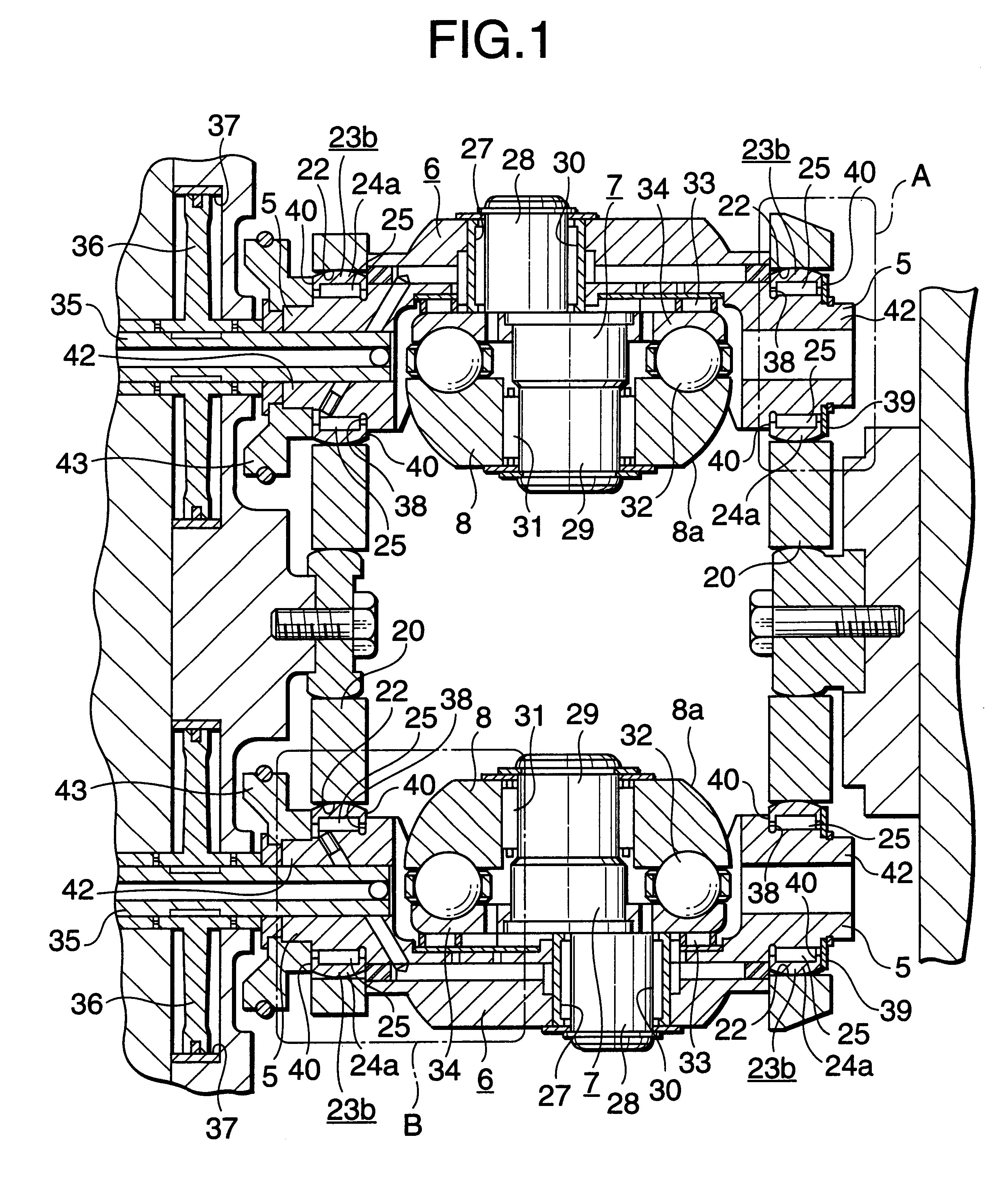
Especially, in the toroidal-type continuously variable transmission according to the invention, the sufficient load capacities of the radial needle roller bearings used to support pivot shafts provided on the two end faces of the respective trunnions inside the circular holes formed in the respective support plates can be secured, the assembling operation of the toroidal-type continuously variable transmission can be facilitated, and the members adjoining the radial needle roller bearings of the toroidal-type continuously variable transmission can be prevented against wear.
In addition, as the radial needle roller bearing, there is used a needle roller bearing of a full complement needle roller bearing which consists of only needle rollers and has no retainer. Therefore, the number of needle rollers can be increased to thereby secure the sufficient load capacities of the radial needle roller bearings without increasing the diameters of the radial needle roller bearings.
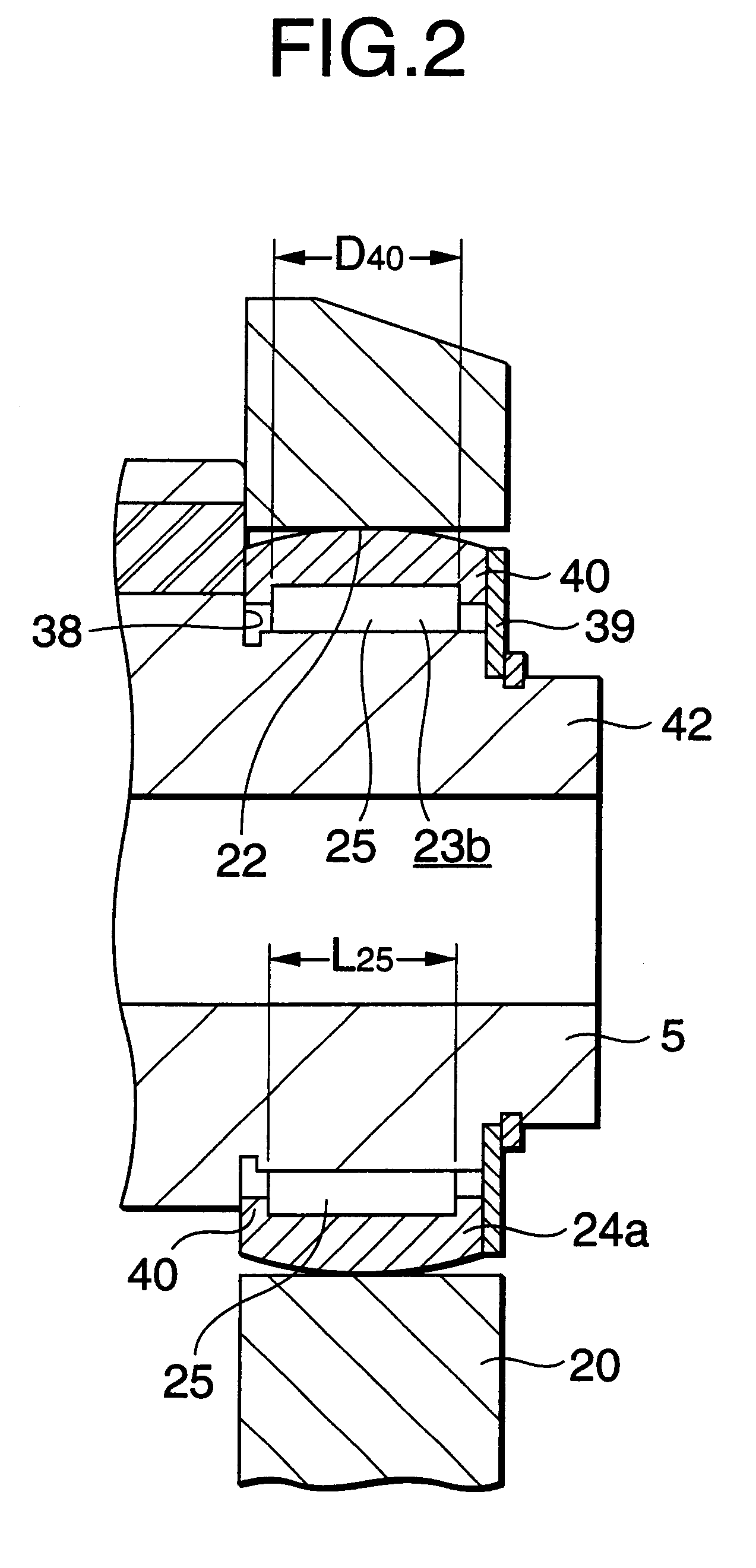
Also, in a state in which a plurality of needle rollers forming the radial needle roller bearing are disposed on the inside diameter side of an outer race, the two end faces of the respective needle rollers in the axial direction thereof are contacted with or are adjacently opposed to flange portions formed on the inner peripheral surfaces of the two end portions of the outer race. Therefore, in a state in which the needle rollers are disposed on the inside diameter side of the outer race, the needle rollers and outer race can be fitted around the pivot shaft. This can facilitate the assembling of the radial needle roller bearing to the pivot shaft.
Further, the axial-direction two end faces of each of the needle rollers are disposed opposed to the flange portions which, similarly to such needle rollers, are formed of hard material. This can prevent the members adjoining the needle roller bearings against excessive wear.
Moreover, in the toroidal-type continuously variable transmission according to the invention, it is possible to facilitate the finishing operation of an outer race raceway which is formed in the inner peripheral surface of an outer race constituting the radial needle roller bearing. Also, the axial-direction dimension of the radial needle roller bearing can be shortened, thereby being able to facilitate the drafting of a design which not only can reduce the size and weight of the whole toroidal-type continuously variable transmission but also can secure the rigidity of the trunnions of the toroidal-type continuously variable transmission.

Problems solved by technology

However, in case of the conventional structure as shown in FIG. 17, not only the assembling operation thereof is complicated but also it is difficult to secure the durability of members which adjoin the radial needle roller bearings 23a, 23a.
Such operation is very troublesome; that is, such troublesome operation, unfavorably, hinders the enhancement in the efficiency of the toroidal-type continuously variable transmission assembling operation, thereby causing an increase in the cost of the present transmission.
Such wear is also undesirable, because it gives rise to the deteriorated durability of the toroidal-type continuously variable transmission.

Method used


Image

  • Toroidal-type continuously variable transmission
  • Toroidal-type continuously variable transmission
  • Toroidal-type continuously variable transmission

Examples


Embodiment Construction

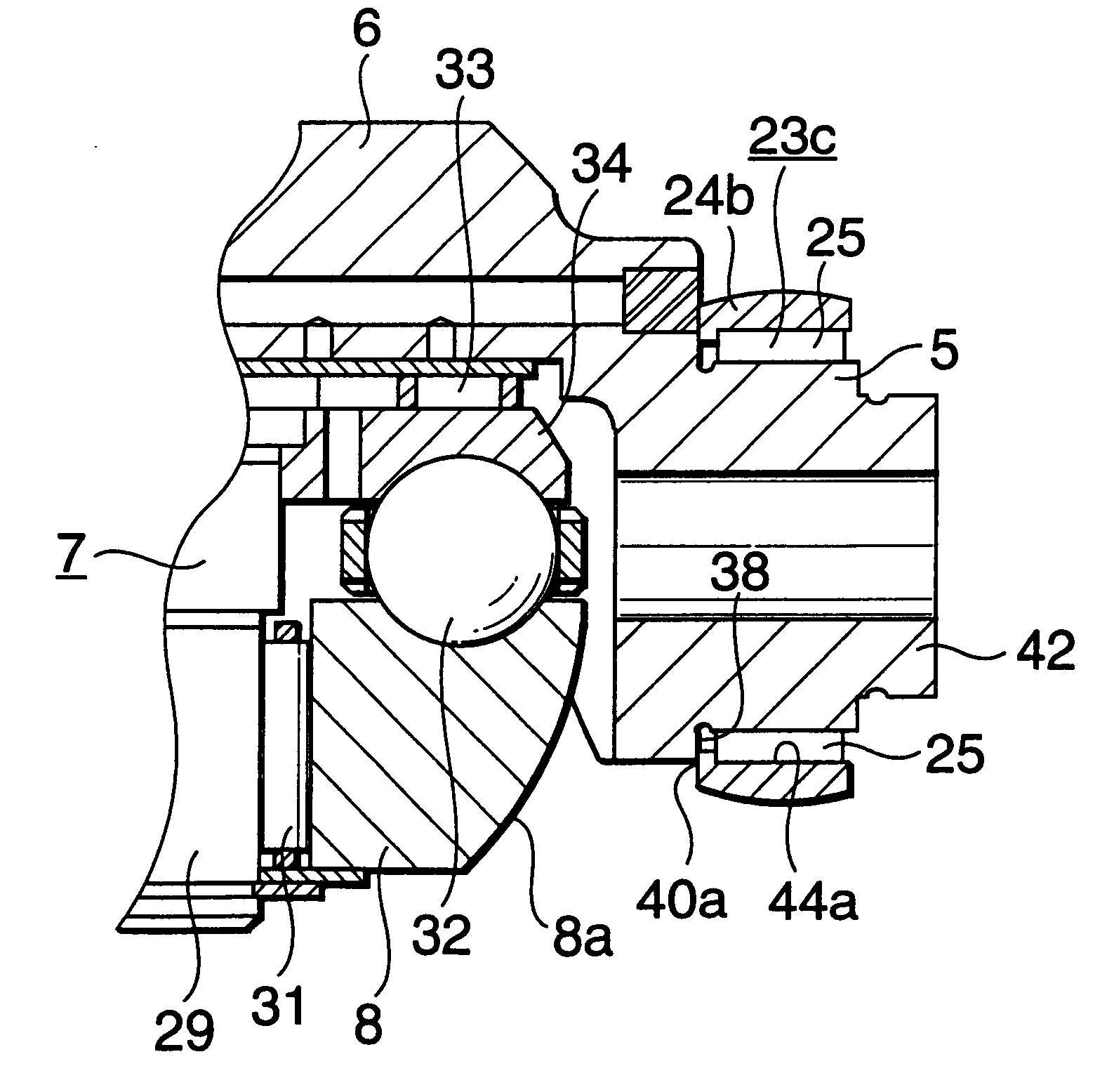
Now, FIGS. 1 to 4 respectively show a first embodiment of a toroidal-type continuously variable transmission according to the invention. By the way, the feature of the invention is the structure of radial needle roller bearings 23b, 23b portions respectively used to support the pivot shafts 5, 5, which are respectively formed in the two end portions of trunnions 6, 6, in the inside portions of circular holes 22, 22 formed in support plates 20, 20. The structures and operations of the other remaining portions of the invention are similar to those of various toroidal-type continuously variable transmissions which have been conventionally known or proposed. Therefore, the description thereof is omitted or simplified and thus the following description will be given mainly of the feature of the invention.

Pivot shafts 5, 5 disposed in the respective two end portions of a pair of trunnions 6, 6 are respectively supported on a pair of support plates 20, 20 in such a manner that they can be ...


PUM


Abstract

In a toroidal-type continuously variable transmission, a plurality of trunnions is respectively swingable about a pair of mutually concentric pivot shafts through a plurality of radial needle roller bearings respectively supporting the pivot shafts. Each of the radial needle roller bearings includes: an outer race interposed between an outer peripheral surface of the pivot shaft and an inner peripheral surface of the circular hole of the support plate, the outer race having an outer peripheral surface formed in a spherically convex surface; and a plurality of needle rollers respectively disposed on the inside diameter side of the outer race. The outer race is formed with an inwardly facing flange portion on the inner peripheral surface of the end portion thereof.

Description

1. Field of the InventionThe present invention relates to an improved toroidal-type continuously variable transmission to be used as a transmission for a car and, in particular, to such transmission having a structure which is easy to assemble and is able to sufficiently secure the load capacities of the support portions of trunnions employed therein.2. Description of the Related ArtIt has been studied to use such toroidal-type continuously variable transmission as shown in FIGS. 13 and 14 as a transmission for a car. This toroidal-type continuously variable transmission is a transmission which is called a half-toroidal-type continuously variable transmission. In the half-toroidal-type continuously variable transmission, for example, as disclosed in Japanese Utility Model Unexamined Publication No. 62-71465 of Showa, an input side disk 2 is supported concentrically with an input shaft 1, while an output side disk 4 is fixed to the end portion of an output shaft 3 disposed concentric...

Claims


Application Information

Patent Timeline
IPC IPC(8): F16H15/38F16H15/32
CPCF16H15/38F16C2361/65
Inventor ITOH, HIROYUKIHIGUCHI, SEIJIGOTO, NOBUOTANAKA, MASAMIKOBAYASHI, NORIHISA
Owner NSK LTD
Learn More