Suspension arm assembly for a vehicle, and vehicle incorporating same

a technology for suspension arm assemblies and vehicles, applied in vehicle arrangements, transportation and packaging, transportation items, etc., can solve the problems of increasing the weight achieve the effect of improving the rigidity of the suspension arm assembly, improving the connection of the pair of pipes with the u-shaped band, and improving the spatial structur

Active Publication Date: 2010-03-11
HONDA MOTOR CO LTD
View PDF25 Cites 11 Cited by
  • Summary
  • Abstract
  • Description
  • Claims
  • Application Information

AI Technical Summary

Benefits of technology

[0021]According to the present invention, the distal end portions (at the exterior of the vehicle body) of the pair of pipes are connected to the convex surface of the U-shaped band, so that the area of the connected surface between each of the pair of pipes and the U-shaped band is increased. Thus, the strength of the connection of the pair of pipes with the U-shaped band is improved.
[0022]Moreover, since the plate portion of the joint member is attached to the pair of pipes so as to cover the U-shaped band from above or below, the joint member, the pipes and the U-shaped band are spatially combined. As a result, the distal end portion of the suspension arm assembly has an improved spatial structure, thereby improving the rigidity of the suspension arm assembly. Accordingly, the rigidity of the suspension arm assembly can be secured. Also, the weight of the suspension arm assembly can be reduced, without employing one or more additional structures, which requires increasing the diameter of each of the pair of pipes and / or the thickness of the boss portion of the joint member.
[0023]In addition, the outer circumferential end portion of the plate portion is bent downwardly in an area adjacent the boss portion, thereby forming a wall. Accordingly, the rigidity of the boss portion of the joint member can be increased. Meanwhile, the wall has an angular U shape, when viewed in a cross-sectional view. Such angular U shape allows the wall portion to be mated and fitted onto the U-shaped band and the pair of pipes. Thus, the distal end portion of the suspension aim assembly has an improved spatial structure, making it possible to secure a higher rigidity.
[0024]Furthermore, a large space is formed between the U-shaped band and the boss portion, so that interference between the knuckle attached to the boss portion and the U-shaped band can be prevented. Such interference may occur during operation of the suspension arm assembly.
[0025]Additionally, when viewed in a side view, the distal end portions of the U-shaped band are formed narrower than other portions thereof, so that interference between the knuckle attached to the boss portion and the U-shaped band can be prevented during operation of the suspension arm assembly.
[0026]Moreover, since the outer circumferential end portion of the plate portion of the joint member is bent downwardly in an area adjacent the boss portion, the rigidity of the boss portion can be increased. In addition, since the height of the distal end portion, at the exterior of the vehicle body, of the outer circumferential end portion of the plate portion is less than that of the other portion thereof, when viewed in a side view, the interference between the knuckle attached to the boss portion and the distal end portion, at the exterior of the vehicle body, of the joint member can be prevented. Accordingly, the moving range of the knuckle can be made wider. The interference occurs when the suspension arm assembly is operated.

Problems solved by technology

Thus, in order to secure the rigidity of the suspension arm assembly, the structure of the suspension arm assembly needs to be firm, for example, by increasing the diameters of the pipes or the thickness of the boss, which disadvantageously leads to an increase in the weight of the suspension arm assembly.

Method used


Image

  • Suspension arm assembly for a vehicle, and vehicle incorporating same
  • Suspension arm assembly for a vehicle, and vehicle incorporating same
  • Suspension arm assembly for a vehicle, and vehicle incorporating same

Examples


Embodiment Construction

[0034]A selected illustrative embodiment of the present invention will now be described, with reference to the drawings. Throughout this description, relative terms like “front”, “rear,”“upper”, “lower”, “above”, “below”, “front”, “back”, and the like are used in reference to a vantage point of an operator of the vehicle, seated on the driver's seat and facing forward. It should be understood that these relative positional terms are used for purposes of illustration, and are not intended to limit the invention.

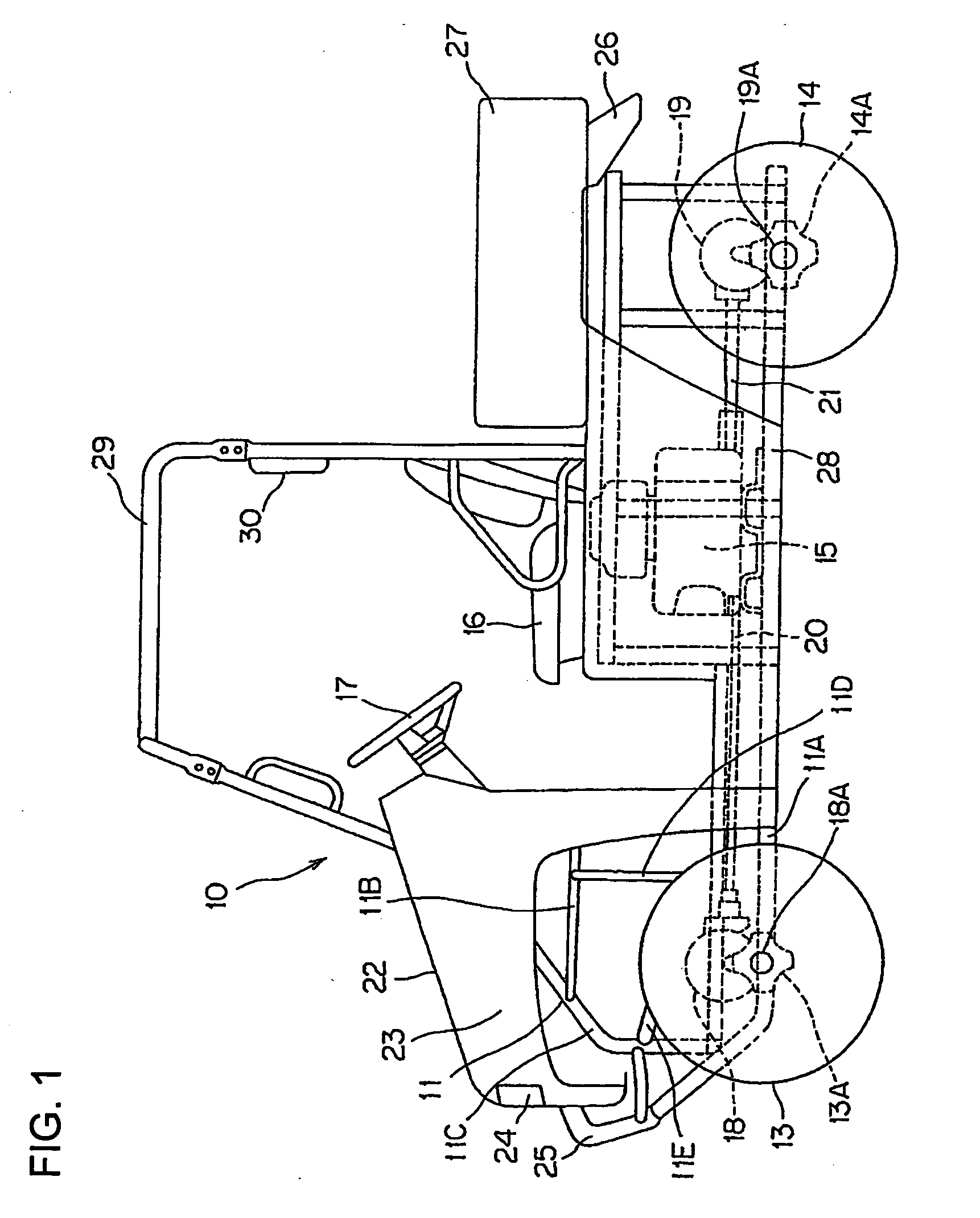
[0035]FIG. 1 is a side plan view of a vehicle 10, which may be a small or a large vehicle, according to an illustrative embodiment of the present invention. The vehicle 10, which may be classified as multi-use vehicle (MUV), is suitable for driving in an off-road environment on rough, undulated ground (unleveled ground).

[0036]The vehicle 10 includes right and left front wheels 13, 13 independently suspended on a vehicle body frame 11 respectively via front suspensions (suspens...


PUM


Abstract

A suspension arm assembly for a vehicle includes a pivot pipe pivotally attached to a vehicle body frame, a pair of pipes extending in a lateral direction of a vehicle body, a joint member attached to distal end portions of the pipes, and a substantially U-shaped band. Proximal end portions of the pipes are connected to the pivot pipe and spaced apart from each other in a front-rear direction, and distal end portions thereof are arranged close to each other, thereby forming a substantially triangular profile. The joint member includes a plate portion and a boss portion having a knuckle attached thereto. The distal end portions of the pipes are operatively connected to a convex surface of the U-shaped band, and the plate portion of the joint member is attached to the pipes for covering the U-shaped band.

Description

CROSS-REFERENCE TO RELATED APPLICATIONS[0001]The present invention claims priority under 35 USC 119 based on Japanese patent application No. 2008-231539, filed on Sep. 9, 2008. The entire subject matter of this priority document, including specification claims and drawings thereof, is incorporated by reference herein.BACKGROUND OF THE INVENTION[0002]1. Field of the Invention[0003]The present invention relates to a suspension arm assembly for a vehicle, and to a vehicle incorporating the same. More particularly, the present invention relates to a suspension arm assembly including a pair of pipes, and a substantially U-shaped band operatively attached to end portions of the pair of pipes, the U-shaped band including a convex surface, and a concave surface facing outwardly of the vehicle body. The invention also relates to a multi-use vehicle incorporating the suspension arm assembly.[0004]2. Description of the Background Art[0005]A number of different vehicle suspension arm assemblies...

Claims


Application Information

Patent Timeline
Patent Type & Authority Applications(United States)
IPC IPC(8): B60P3/00B60G3/06B60G3/20
CPCB60G7/001B60G2200/144B60G2300/13B60G2206/012B60G2206/124B60G2204/129
Inventor KUWABARA, NAOKI
Owner HONDA MOTOR CO LTD
Why Eureka
Try Eureka