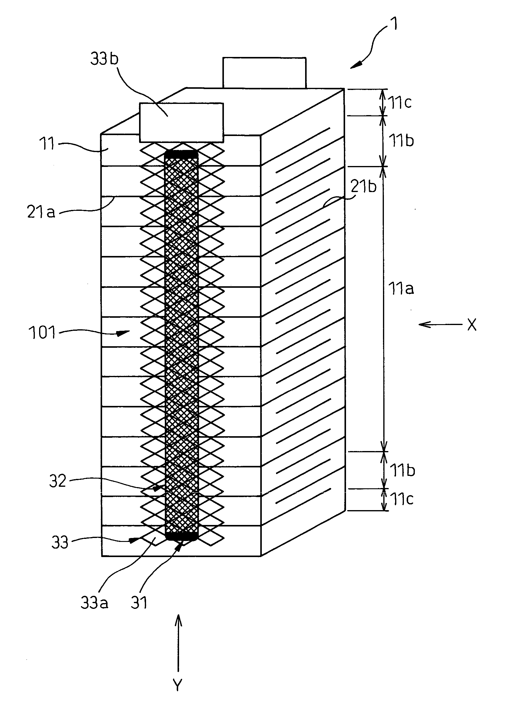
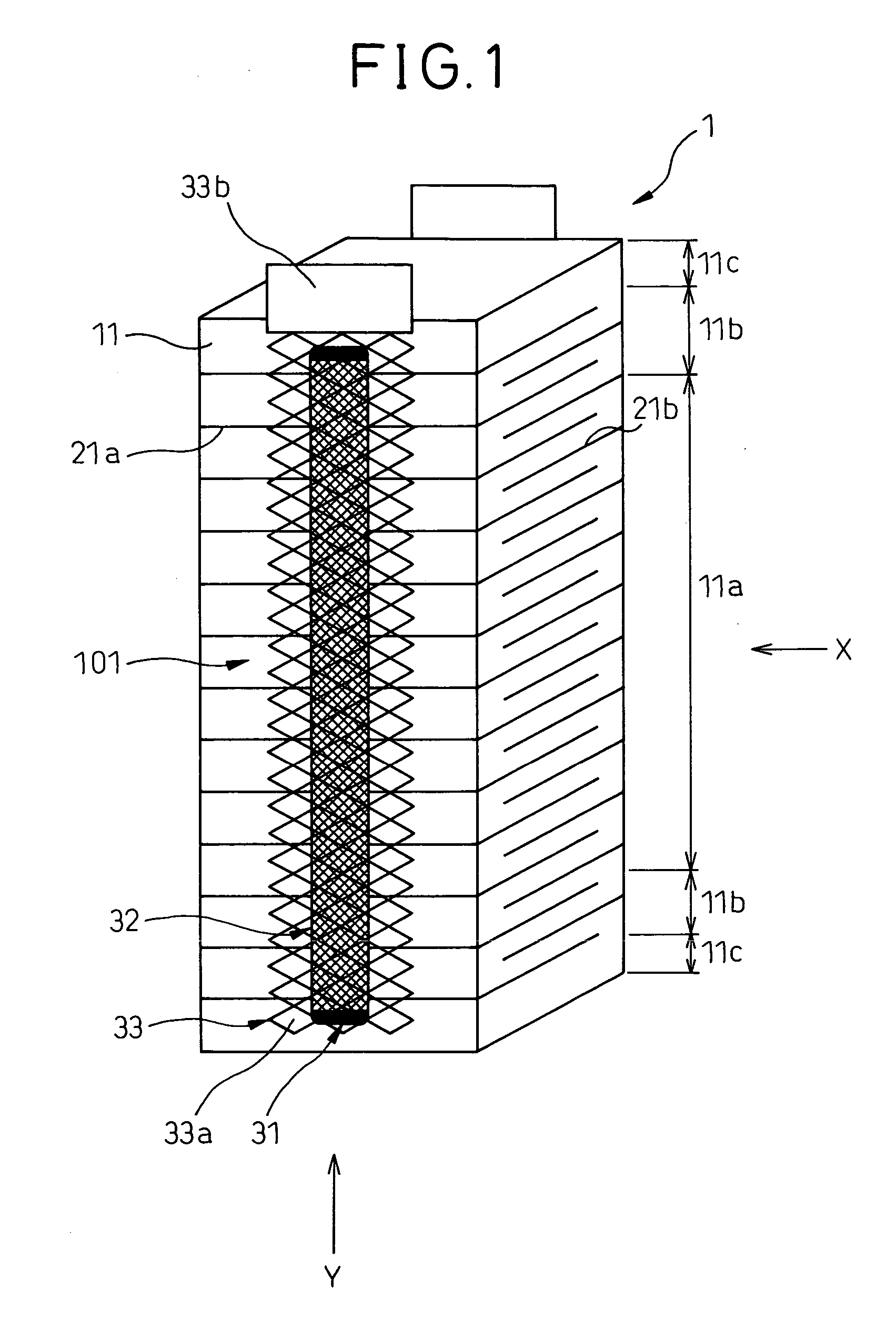
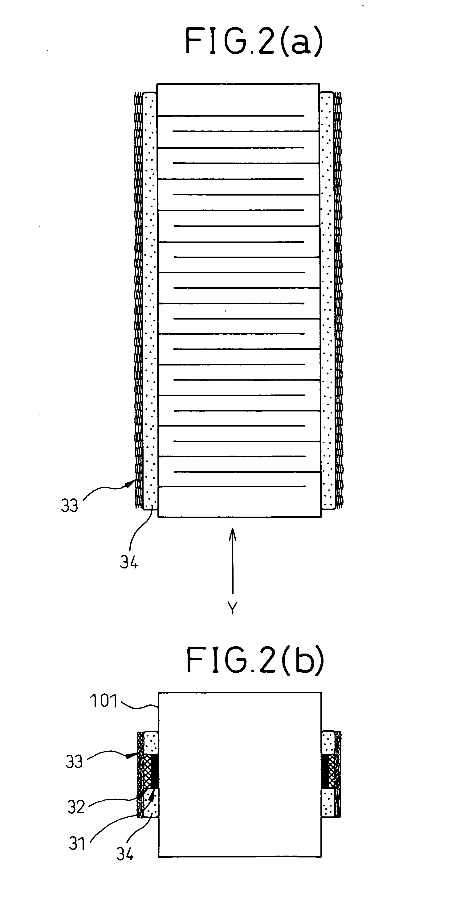
[0007] Thereby, although an adhering strength of the
electrically conductive adhesive member is generally weak in comparison with
soldering or
brazing, the first external electrode layer strongly connects to the laminated-type piezoelectric element, as the electrically conductive adhesive member penetrates into the opening portion of the first external electrode layer to form a connection in the shape of an anchor. Further, as the width of the electrically conductive adhesive member is narrower than the width of the first external electrode layer, the electrical
conductivity for the internal electrode
layers can be secured by a part of the first external electrode layer which is not fixed to the electrically conductive adhesive member, even when a part of the first external electrode layer fixed to the electrically conductive adhesive member is broken by a displacement of the piezoelectric
layers and the like. Therefore, the laminated-type piezoelectric element can be provided, where the connecting strength between the internal electrode layers formed at the laminated-type piezoelectric element and the first external electrode layer is high, and the displacement properties do not easily change even if a part of the first external electrode layer was broken.
[0016] Further, according to the invention of claim 11, the laminated-type piezoelectric element is provided, wherein a non-opening portion, where the opening portion is not formed, is formed at an end portion of the first external electrode layer. Thereby, the connection with an outer device can be made easy.
[0017] According to the invention of claim 12, the laminated-type piezoelectric element is provided, wherein a second external electrode layer intervenes between the electrically conductive adhesive member and the first external electrode layer, especially wherein the second external electrode layer is composed of a
metal composed of at least one
metal selected from silver,
palladium,
platinum,
copper, gold and
nickel, or an
alloy thereof. Thereby, a thermal stress applied from the piezoelectric layers to the first external electrode layer can be decreased in comparison with a case where the first external electrode layer is directly connected to the piezoelectric layers, because a coefficient of
thermal expansion of the second external electrode layer is between the coefficients of
thermal expansion of the piezoelectric layer and the first external electrode layer, and functions as a layer for the relaxation of a thermal stress.
[0018] According to the invention of claim 14, the laminated-type piezoelectric element is provided, wherein an insulating resin member intervenes in a gap between the first external electrode layer and the internal electrode layer, which is formed so that the width of the electrically conductive adhesive member is narrower than the width of the first external electrode layer, especially wherein the insulating resin member is composed of a
silicone resin, an
epoxy resin, a urethane resin, a
polyimide resin, a polyamideimide resin or a
polyester resin. Thereby, phenomena of electrical
discharge caused by repeating electrical
conductivity between the first external electrode layer and the internal electrode layer can be prevented, because an electrical insulation can be formed between the first external electrode layer and the internal electrode layer there.
[0019] According to the present invention of claim 16, the laminated-type piezoelectric element is provided, where the laminated-type piezoelectric element is formed by connecting laminated-type piezoelectric units. Even in such a manner, the present invention can provides the laminated-type piezoelectric element where the connecting strength between the internal electrode layers formed in the laminated-type piezoelectric element and the first external electrode layer is high, and displacement properties do not easily change even if a part of the first external electrode layer was broken.
[0020] If the laminated-type piezoelectric element is utilized for a
fuel injection device according to the present invention of claim 17, the
fuel injection device with an excellent durability can be provided, because the connecting strength between the internal electrode layers formed in the laminated-type piezoelectric element and the first external electrode layer is high, and displacement properties do not easily change even if a part of the first external electrode layer was broken.


