Engine-driven generator

a technology of engine-driven generators and generators, which is applied in the direction of engine starters, liquid fuel engines, muscle operated starters, etc., can solve the problems of difficult cooling of cooling fans and obstacle to reducing the number of members, and achieve the effect of improving the cooling performance of cooling fans

Active Publication Date: 2016-09-29
HONDA MOTOR CO LTD
View PDF36 Cites 11 Cited by
  • Summary
  • Abstract
  • Description
  • Claims
  • Application Information

AI Technical Summary

Benefits of technology

[0014]The annular portion is molded integrally with the centrifugal fan. The guide protrudes outwardly from the annular portion through the opening of the fan cover. The cooling air is directed fr

Problems solved by technology

Due to this arrangement, it is difficult for the cooling fan to deliver a cooling air to the crankcase; hence, some measures should be taken to cool

Method used


Image

  • Engine-driven generator
  • Engine-driven generator
  • Engine-driven generator

Examples


Embodiment Construction

[0025]It will be appreciated that the terms “front”, and “rear” as used herein indicate a side toward a recoil starter, and a side toward an engine.

[0026]An engine-driven generator 10 in an embodiment of the invention is discussed below.

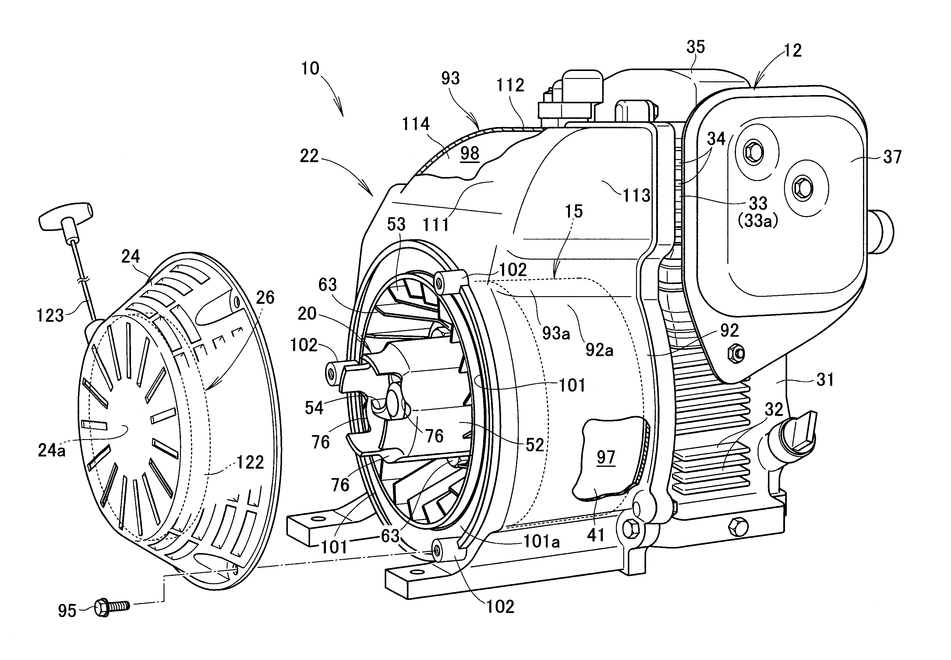
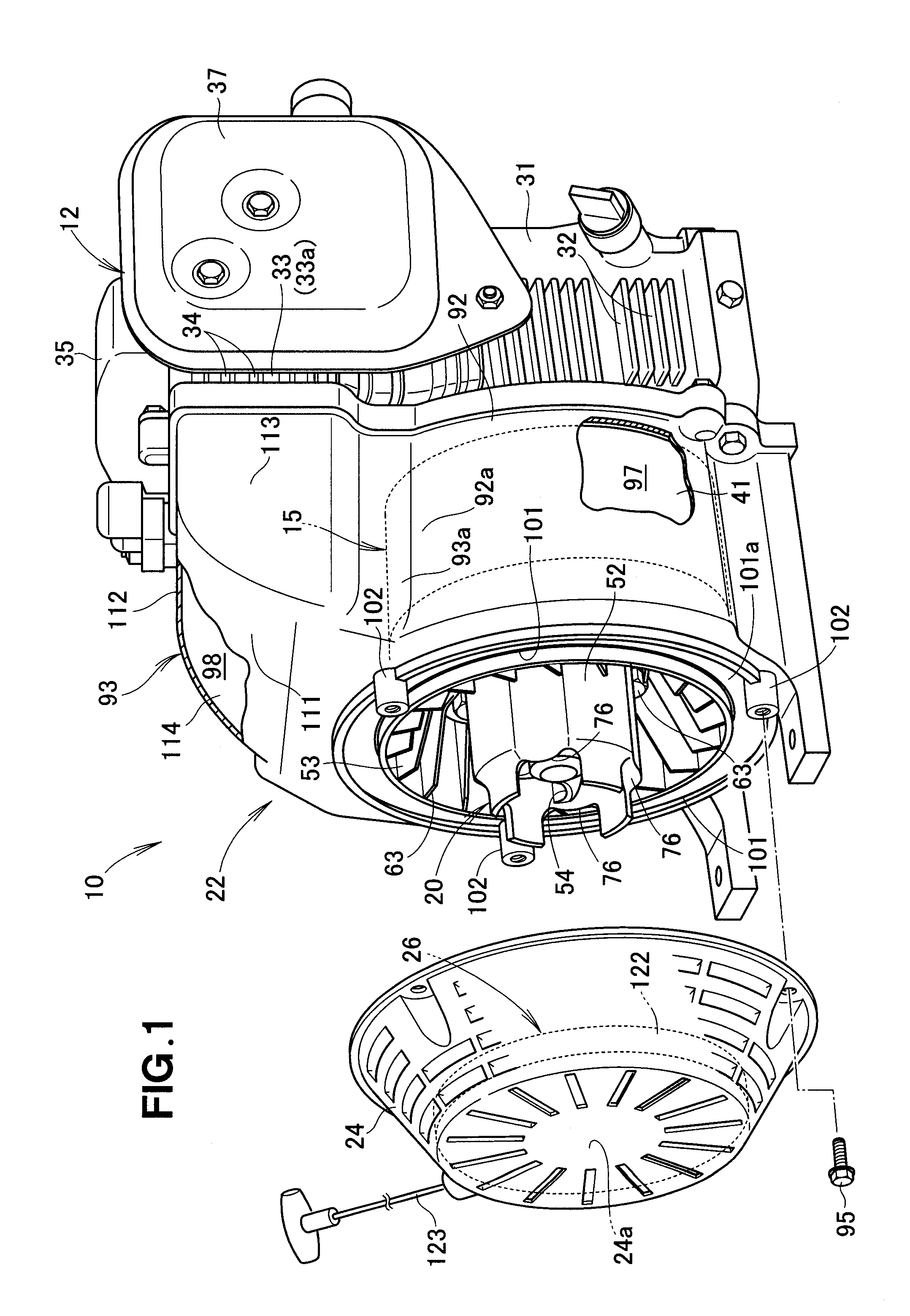
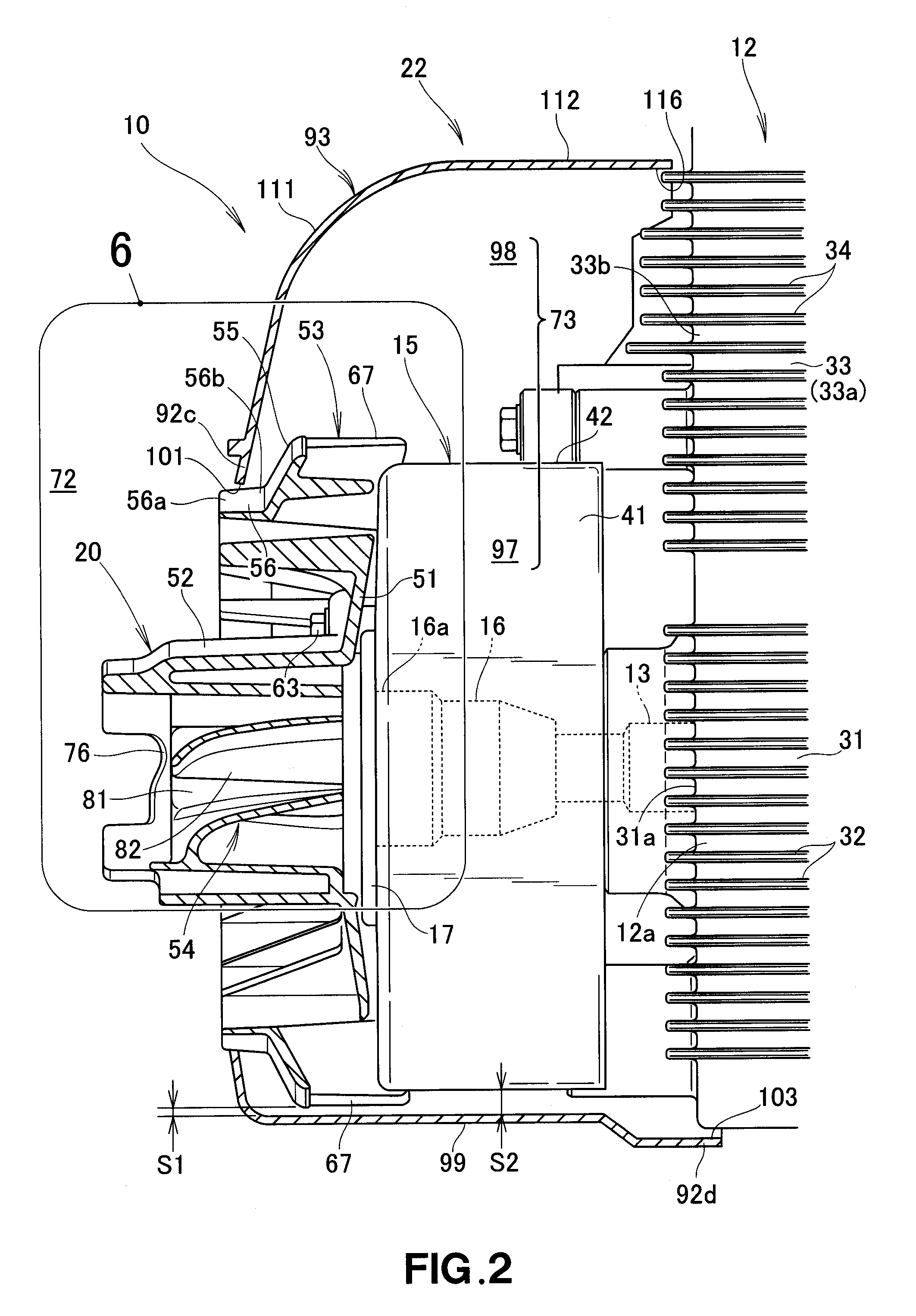
[0027]As shown in FIGS. 1 and 2, the engine-driven generator 10 includes an engine 12 having a crankshaft 13 acting as an engine output shaft, and a generator unit 15 having a drive shaft 16 connected to the crankshaft 13. The generator 10 also includes a cooling fan 20 connected to the drive shaft 16, and a fan cover 22 covering the cooling fan 20 and the generator unit 15. The generator 10 further includes a recoil cover 24 attached to the fan cover 22, and a recoil starter 26 attached to the recoil cover 24.

[0028]The engine 12 includes a crankcase 31 defining a lower part of the barrel, and a cylinder block 33 defining an upper part of the barrel. The crankshaft 13 is rotatably supported by the crankcase 31. The cylinder block 33 is formed on the ...


PUM


Abstract

An engine-driven generator includes an engine having a crankshaft, a generator unit having a drive shaft connected to the crankshaft, a cooling fan connected to the drive shaft, and a recoil starter engageable with the cooling fan. The cooling fan includes a starting pulley engageable with the recoil starter, a centrifugal fan formed on a circumferential outer side of the pulley, and a mixed flow fan formed on a circumferential inner side of the pulley. The pulley, the centrifugal fan, the mixed flow fan are molded integrally with one another.

Description

FIELD OF THE INVENTION[0001]The present invention relates to an engine-driven generator including an engine, a generator unit connected to the engine, and a cooling fan connected to the generator unit.BACKGROUND OF THE INVENTION[0002]A well-known engine for a working machine includes a crankshaft on which a cooling fan is coaxially mounted. A staring pulley is coaxially mounted on the cooling fan. The pulley is engageable with a recoil starter. The pulley is hollow and the cooling fan is formed integrally with an outer circumference of the pulley.[0003]To start the engine, a cable of the recoil starter is manually pulled by an operator to rotate the pulley (i.e., the cooling fan). The rotation of the cooling fan rotates the crankshaft to thereby start the engine. Upon the starting of the engine, the crankshaft rotates the cooling fan, such that the cooling fan cools a cylinder block of the engine by delivering a cooling air thereto. Such an engine is disclosed in, for example, in JP...

Claims


Application Information

Patent Timeline
IPC IPC(8): F02B63/04F04D17/16
CPCF04D17/16F02B63/04F02D29/06F02N3/02H02K7/18H02K9/06F01P1/06F02N11/04F02N15/006F02B63/044F04D25/082F04D25/166F01P5/04F04D29/5806
Inventor KASE, TAKUOTAKAHASHI, YUKI
Owner HONDA MOTOR CO LTD
Why Eureka
Try Eureka