Device and method for injecting fluid into a rotating fluidized bed

a fluidized bed and fluid injection technology, which is applied in the direction of furnaces, lighting and heating apparatuses, furnace types, etc., can solve the problems of difficult to feed in and discharge solid particles without, difficult to obtain a very high centrifugal force, and strong vibrations limiting the speed of rotation of this devi

Inactive Publication Date: 2010-08-05
TOTAL RES & TECH FELUY
View PDF4 Cites 29 Cited by
  • Summary
  • Abstract
  • Description
  • Claims
  • Application Information

AI Technical Summary

Benefits of technology

[0005]The present invention comprises a device for feeding and discharging solid particles in a rotating or fixed circular reaction chamber and a device (also called an injection device) for feeding in one or more gaseous or liquid fluids, enabling all or part of the fluid or fluids to be injected along the fixed or rotating circular wall of the reaction chamber, in the form of fluid jets, preferably in directions forming an angle less than 45° with planes tangential to the circular wall, or in a succession of thin layers passing along the fixed circular wall so as to cause this fluid or these fluids that entrain solid particles to rotate along the fixed or rotating circular wall in a rotating movement of which the centrifugal force pushes them toward the fixed circular wall along which they form a rotating fluidized bed. It also includes a device for discharging this fluid or these fluids comprising a central rotating tube, also called a central rotating chimney or central discharge chamber, passing through or entering longitudinally inside the fixed or rotating circular reaction chamber, this central rotating tube having one or more openings enabling this fluid or these fluids to be discharged centrally, and rotating in the same direction and preferably more rapidly than the average speed of the fluid or fluids and of the rotating fluidized bed so as to increase the centrifugal force that pushes, toward the rotating or fixed circular wall, solid particles that are entrained by the fluid or fluids toward the central chimney.

Problems solved by technology

It is easy to obtain a rotating fluidized bed by supporting it on a rotating porous cylinder, but non-uniformity of the fluidized bed may bring about strong vibrations limiting the speed of rotation of this device and it is not easy to feed in and discharge solid particles without their being entrained by the fluid, when the particles are very fine.
In practice, friction of the fluid along the central chimney makes it difficult to obtain a very high centrifugal force close to the central chimney with too high a fluid flow rate, which may bring about entrainment of the finer solid particles in the central chimney.

Method used


Image

  • Device and method for injecting fluid into a rotating fluidized bed
  • Device and method for injecting fluid into a rotating fluidized bed
  • Device and method for injecting fluid into a rotating fluidized bed

Examples


Embodiment Construction

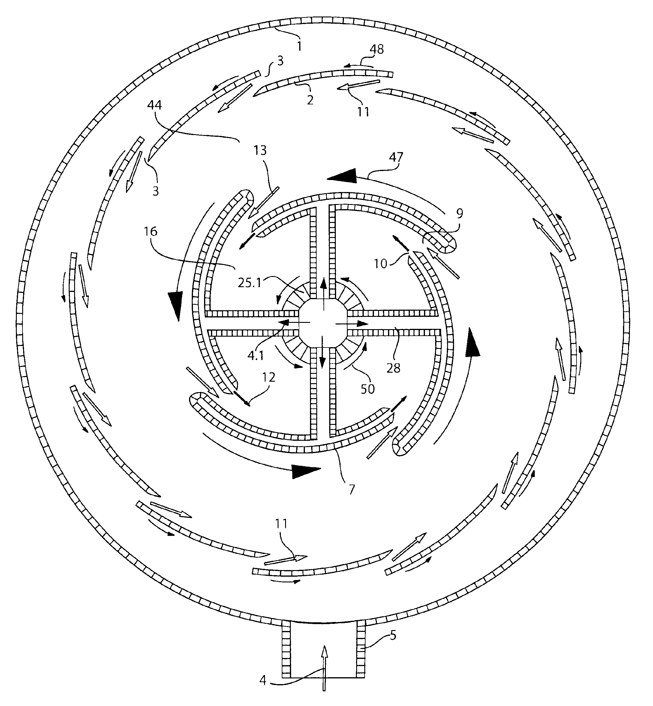
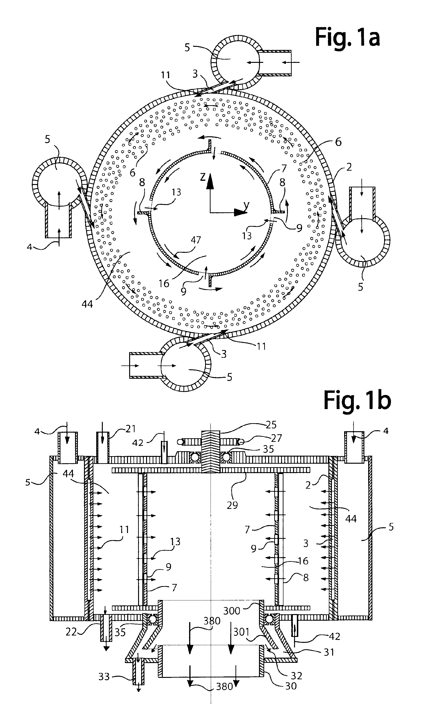
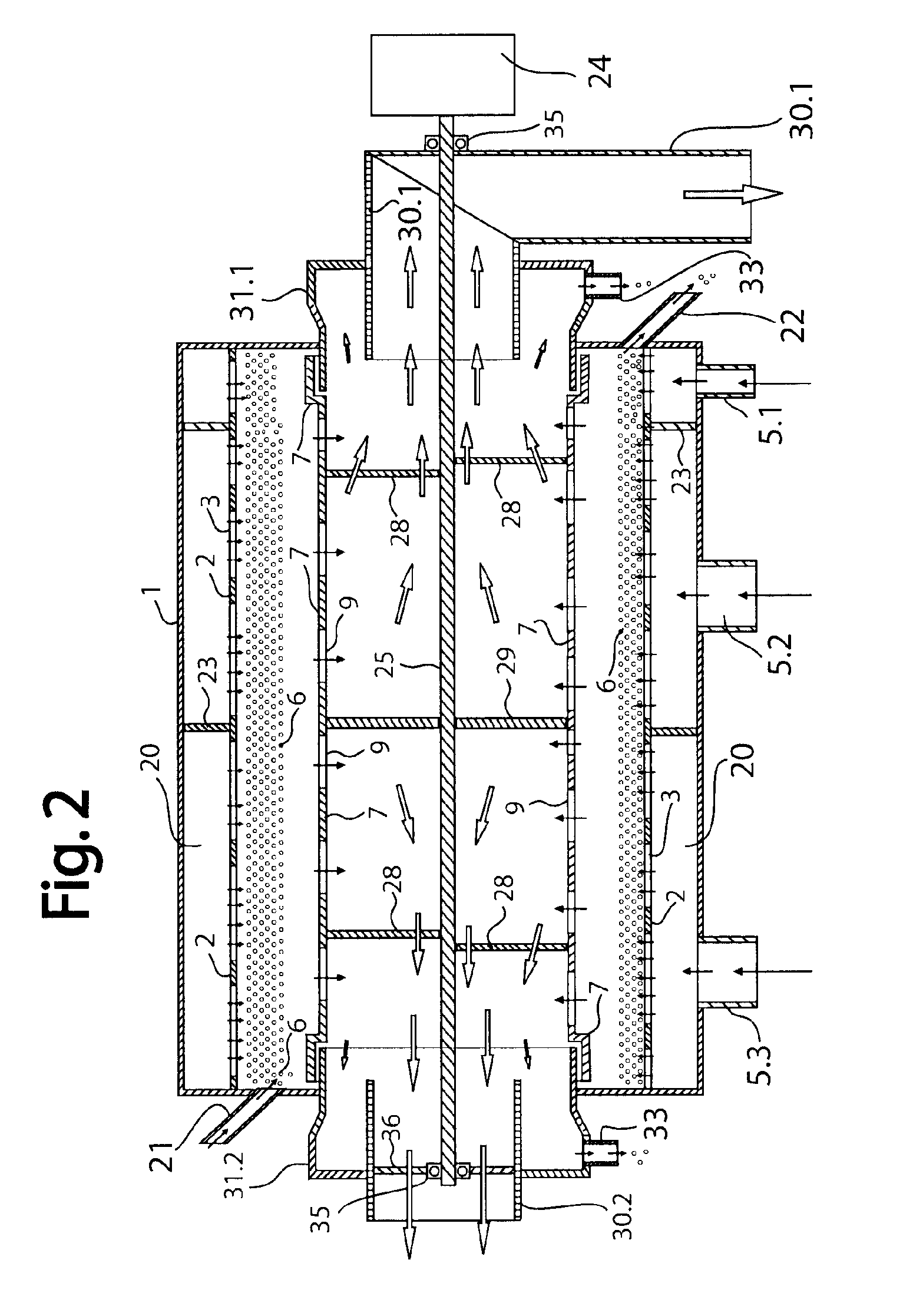
[0063]According to a particular embodiment of the invention, the device with a rotating fluidized bed comprises:[0064]a device for feeding into a fixed circular chamber one or more gaseous or liquid fluids, disposed about the fixed circular wall of said circular chamber and a device for allowing said fluid or fluids to be discharged centrally,[0065]a device for feeding solid particles into said circular chamber and a device for discharging said solid particles,[0066]said device for feeding said fluid or fluids comprising openings distributed along said fixed circular wall (or fluid injectors distributed about said fixed circular wall) allowing said fluid or fluids to be injected in directions preferably forming an angle less than 45° with planes tangential to said circular wall, said fluid or fluids being able to rotate inside said circular chamber along said circular wall before being able to be discharged centrally and that can cause solid particles fed in by said feed device to r...


PUM

PropertyMeasurementUnit
angleaaaaaaaaaa
angle of incidenceaaaaaaaaaa

Abstract

A device for discharging, through a central rotating chimney, fluids from a fluidized bed driven in a rotational movement in the same direction by the rotation of the outer circular wall of a reaction chamber and / or by injection of part of these fluids along the circular wall of a fixed or rotating chamber, and methods for catalytic polymerization, drying, or other treatments of solid particles in suspension in a rotating fluidized bed or for cracking or other catalytic conversions of fluids using this device.

Description

TECHNICAL FIELD OF THE INVENTION[0001]The present invention relates to a device with a rotating fluidized bed comprising a rotating device for discharging a fluid or fluids passing through the rotating fluidized bed. In particular, the present invention relates to a device for discharging, through a central rotating chimney, one or more gaseous or liquid fluids from a rotating or fixed reaction chamber along which the fluid or fluids is / are injected and cause a fluidized bed to rotate while passing through it. The present invention also relates to methods for catalytic polymerization, drying, impregnation, coating, combustion, gasification, classification or other treatments of solid particles suspended in a rotating fluidized bed, or cracking, dehydrogenation or other catalytic conversions of fluids using this device.TECHNICAL BACKGROUND TO THE INVENTION[0002]In order to obtain a dense fluidized bed, traversed by a fluid flow, the pressure exerted by the fluid on solid particles mu...

Claims


Application Information

Patent Timeline
Patent Type & Authority Applications(United States)
IPC IPC(8): C08F110/00B01J8/18B01J8/38B05D1/00
CPCB01J2/006B01J2/12C08F10/00B01J8/002B01J8/003B01J8/0055B01J8/14B01J8/1818B01J8/36B01J8/386B01J2208/00761B01J2208/00769B01J2208/00867B01J2208/00876B01J2208/00884C08F2/01
Inventor DE BROQUEVILLE, AXELDE WILDE, JURAY
Owner TOTAL RES & TECH FELUY
Why Eureka
Try Eureka