Intelligent Area Lighting System

Active Publication Date: 2010-08-12
CARMANAH TECHNOLOGIES INC
View PDF22 Cites 236 Cited by
  • Summary
  • Abstract
  • Description
  • Claims
  • Application Information

AI Technical Summary

Benefits of technology

[0015]It is a further object of the invention to provide lighting for a user of an area that will gradually and progressively illuminate the user's path,

Problems solved by technology

However, in some parts of the world, particularly at certain times of the year, the amount of sunlight available to charge a solar-powered system may simply not provide sufficient energy to power a lighting system for an extended period of time at night or in low light conditions.
While more energy may be obtained by using larger solar panels, such solution is restricted by space and cost considerations.
Motion-sensitive lighting is often used in infrequently accessed areas, where continuous lighting may be unnecessary and expensive.
Such motion-sensitive lighting is often intended as a deterrent and is therefore often very bright and harsh, tending to suddenly flood a particular area with light.
Such illumination again tends to be relatively sudden and harsh, which can actually hinder a user's efforts, for example, as he seeks a keyhole to unlock a door.
In the context of a person travelling

Method used


Image

  • Intelligent Area Lighting System
  • Intelligent Area Lighting System
  • Intelligent Area Lighting System

Examples


Embodiment Construction

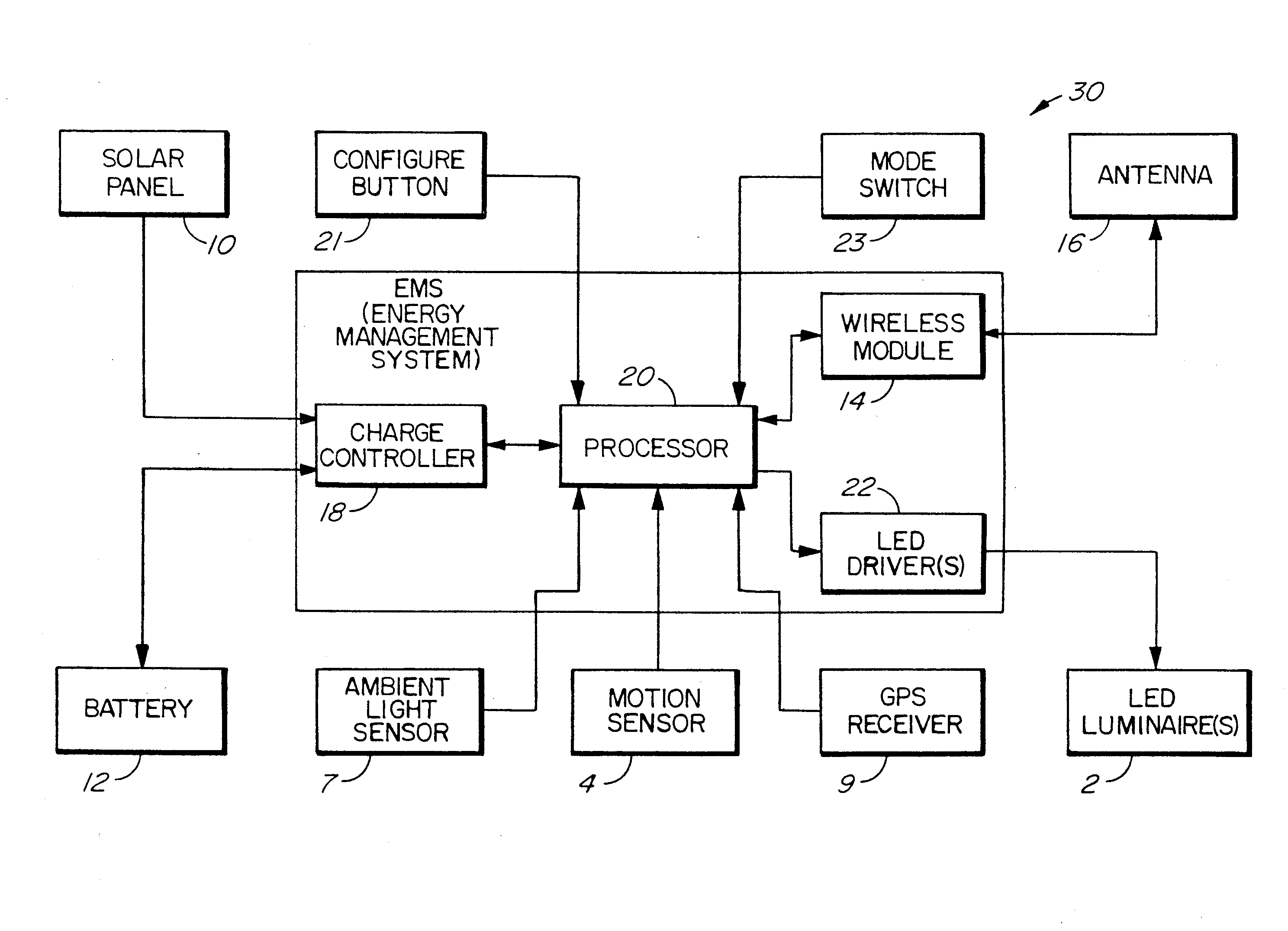
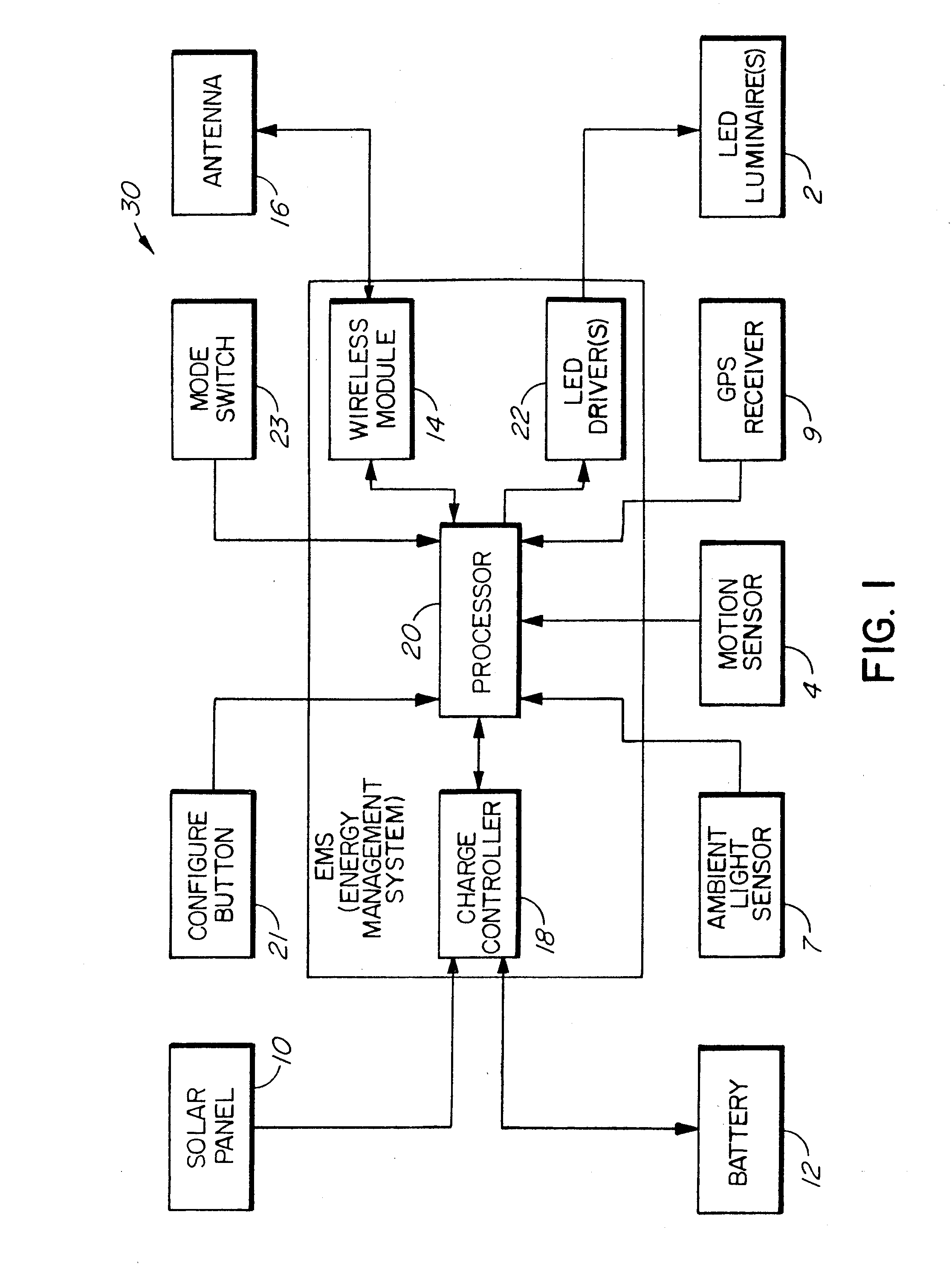
[0038]The basic building block according to the preferred embodiment of the invention is a lighting element 30, whose components are illustrated in the block diagram is of FIG. 1. It is to be understood that in use, a plurality of such lighting elements 30 are deployed in an area to be lighted.

[0039]Lighting element 30 comprises a collection of components enabling the functionality of the invention. In the preferred embodiment, the components are mounted on or within a pole (see FIG. 3), although it is within the scope of the invention to provide a ground-based lighting element that is adapted to rest on the ground or to be anchored in place on the ground. Ground-based lighting is often more appropriate and introduces less light pollution into the environment. It will be appreciated that a combination of pole-mounted and ground-based lighting elements 30 may seamlessly be combined in a lighting network as no aspect of the invention depends on the physical housing of the lighting ele...


PUM


Abstract

An area lighting system is composed of a plurality of lighting elements that are responsive to the movement and progression of a user through the area. Each lighting element comprises at least one light, means for powering the lighting element, a processor, communication means and is associated with a motion sensor. Detection of a user is communicated to other lighting elements that provide an appropriate level of illumination depending on the distance from the user. The lighting elements are substantially self-configurable and may be set for either a radial proximity lighting protocol or a path network lighting protocol.

Description

FIELD OF THE INVENTION[0001]The invention relates to a method and apparatus for intelligent area lighting. More specifically, it relates to a plurality of lighting systems that are configurable to sequentially and gradually illuminate an area as a user moves through it.BACKGROUND OF THE INVENTION[0002]As people look to conserve energy by reducing power consumption, solar energy becomes a viable option to provide power for lighting systems in public areas. However, in some parts of the world, particularly at certain times of the year, the amount of sunlight available to charge a solar-powered system may simply not provide sufficient energy to power a lighting system for an extended period of time at night or in low light conditions. While more energy may be obtained by using larger solar panels, such solution is restricted by space and cost considerations. It is therefore desirable to use a lighting system that conserves as much energy as possible, by selectively activating only when...

Claims


Application Information

Patent Timeline
IPC IPC(8): H01K1/62H05B37/02H05B39/00H05B41/36
CPCY02B20/44H05B37/0245Y02B20/72Y02B20/48H05B37/0272H05B37/0227H05B47/115H05B47/13H05B47/175H05B47/19H05B47/195Y02B20/40
Inventor BOURQUIN, SEANHORTSING, DAMIENJOHNSTON, BROCK
Owner CARMANAH TECHNOLOGIES INC
Why Eureka
Try Eureka