Turbocharger diffuser

Inactive Publication Date: 2010-08-12
BORG WARNER INC
View PDF2 Cites 20 Cited by
  • Summary
  • Abstract
  • Description
  • Claims
  • Application Information

AI Technical Summary

Benefits of technology

[0015]The exemplary embodiments of the turbocharger diffuse fluid over a desired length of a diffuser while maintaining the geometric package or envelope. The diffuser can have a curved shape or other bend to maintain the desired length for diffusing and/or to

Problems solved by technology

Additionally, due to the resulting high velocity of flow, turbochargers are subjected to noise and vibration.
Such conditions can have a detrimental Affect on the components of the turbocharger, particularly on the rotating parts such as the turbine rotor, which can lead to failure of the system.
First, the market demands that all components of the power plant of either a passenger car or truck, including the turbocharger, must provide reliable operation for a much longer period than was demanded in the past.
The Hiroyuki system also suffers from the drawback of requiring a large env

Method used


Image

  • Turbocharger diffuser
  • Turbocharger diffuser
  • Turbocharger diffuser

Examples


Example

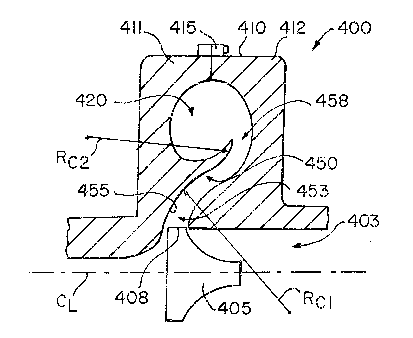
[0038]Embodiments of the invention are directed to diffusion in a turbocharger for delivery of a compressed fluid to an internal combustion engine. Aspects of the invention will be explained in connection with a compressor section having a particular diffuser and scroll, but the detailed description is intended only as exemplary. Exemplary embodiments of the invention are shown in FIGS. 4-9, but the present invention is not limited to the illustrated structure or application.

[0039]Referring to FIG. 4, a turbocharger 400 has a compressor housing 410 connected to center and turbine housings (not shown). The compressor housing 410 has a compressor wheel or impeller 405 rotatably mounted within an impeller chamber 403. The turbocharger 400 has various other features which are not shown in FIG. 4, such as a turbine operatively connected to the engine exhaust manifold, the compressor housing 410 being operatively connected to the engine air intake manifold, and a shaft connecting the turb...


PUM


Abstract

A housing (410, 510, 610, 700, 800, 900) for a turbocharger (400, 500, 600) is provided. The housing (410, 510, 610, 700, 800, 900) has an impeller chamber (403, 503, 603), diffuser (450, 550, 650, 750, 850, 950) and scroll (420, 520, 620, 720, 820, 920) in fluid communication with each other. The diffuser (450, 550, 650, 750, 850, 950) can have a curved shape and/or a bend (455) in proximity to a tip (408, 508, 608, 609) of the impeller (405, 505, 605). The curved shape can be defined by one or more radii of curvature (RC, RC1, RC2). The diffuser (450, 550, 650, 750, 850, 950) can extend in a radial direction that is non-orthogonal to the center line of the turbocharger (400, 500, 600). The housing (410, 510, 610, 700, 800, 900) can be for a compressor section of the turbocharger (400, 500, 600).

Description

FIELD OF THE INVENTION[0001]This invention is directed to a turbocharging system for an internal combustion engine and more particularly to a diffuser of a turbocharging system.BACKGROUND OF THE INVENTION[0002]Turbochargers are a type of forced induction system. They compress the air flowing into an engine, thus boosting the engine's horsepower without significantly increasing weight. Turbochargers use the exhaust flow from the engine to spin a turbine, which in turn drives an air compressor. Since the turbine spins about 30 times faster than most car engines and it is hooked up to the exhaust, the temperature in the turbine is very high. Additionally, due to the resulting high velocity of flow, turbochargers are subjected to noise and vibration. Such conditions can have a detrimental Affect on the components of the turbocharger, particularly on the rotating parts such as the turbine rotor, which can lead to failure of the system.[0003]Turbochargers are widely used on internal combu...

Claims


Application Information

Patent Timeline
IPC IPC(8): F02B33/40F04D29/44
CPCF01D9/026F04D29/444F05D2250/314F05D2250/71F05D2220/40F04D29/441F05D2250/52
Inventor SWEETLAND, PATRICKGRABOWSKA, DAVID G.SEKULARAC, ALEKSANDARROBY, STEPHEN I.
Owner BORG WARNER INC
Why Eureka
Try Eureka