Microendoscope and methods of use

a micro-endoscope and endoscope technology, applied in medical science, surgery, vaccination/ovulation diagnostics, etc., can solve the problem of limited space requirements and current endoscope designs

Inactive Publication Date: 2010-08-12
LUMINUS VENTURES
View PDF14 Cites 80 Cited by
  • Summary
  • Abstract
  • Description
  • Claims
  • Application Information

AI Technical Summary

Benefits of technology

[0007]In accordance with the present invention, a microendoscope assembly is provided. In general, the microendoscope comprises: an outer cylindrical guide tube defining an internal passageway having an exterior diameter of no greater than 1 mm; a first internal cylindrical tube defining a working channel having an interior diameter of no less than 0.5 mm; a second internal cylindrical tube defining a image guide and housing a lens; and an illumination bundle comprising optic fibers.
[0008]In certain aspects, because the cannula tube is of such a small outer diameter, the physician can manipulate the tube from the proximal end in order to guide the microendoscope to the desired location within a subject.
[0009]In certain embodiments, in operation of the microendoscope of the invention, the microendoscope may be placed, e.g., in a duct in a subject's breast with real-time visualization during placement. The physician can view the interior of the duct, as the endoscope passes on its way through the duct to the area of interest. Once at the duct area of interest, the physician can insert micro-instruments into working channel of the microendoscope, as desired while maintaining real-time imaging of the site of interest. When the manipulation of the micro-instrument is completed, the entire assembly may be removed from the duct and breast.
[0010]These and other aspects of the invention will be more clearly understood with reference to the following preferred embodiments and detailed description.

Problems solved by technology

However, current endoscope designs are limited in the small spaces required.

Method used


Image

  • Microendoscope and methods of use
  • Microendoscope and methods of use

Examples


examples

[0034]The present invention is described in more detail with reference to the following non-limiting examples, which are offered to more fully illustrate the invention, but are not to be construed as limiting the scope thereof. The principles, embodiments and modes of operation of the present invention have been described in the foregoing specification. For example, the present invention is not limited to the particular dimensions, materials, or uses described, except as explicitly defined in the claims. Instead, the embodiments described here should be regarded as illustrative rather than restrictive. Variations and changes may be made by others without departing from the scope of the present invention as defined by the following claims.

example

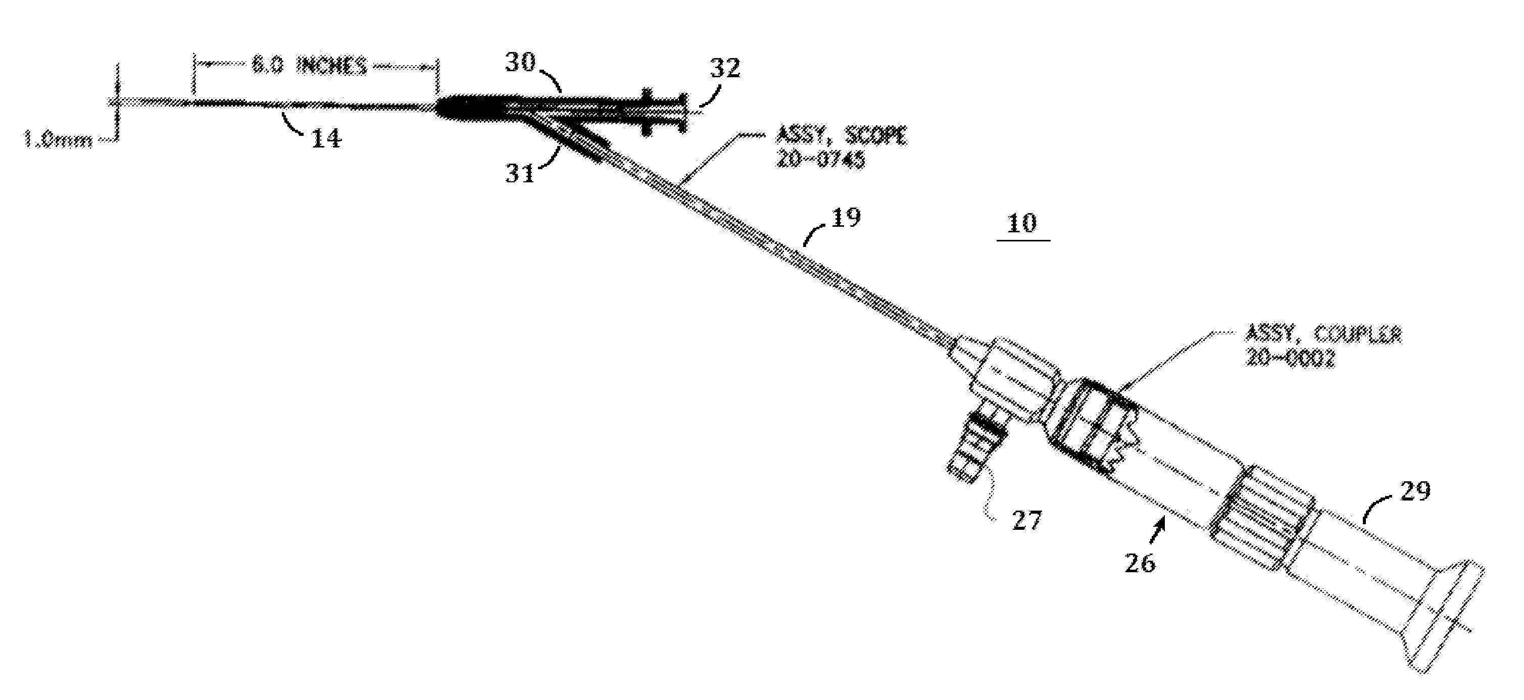
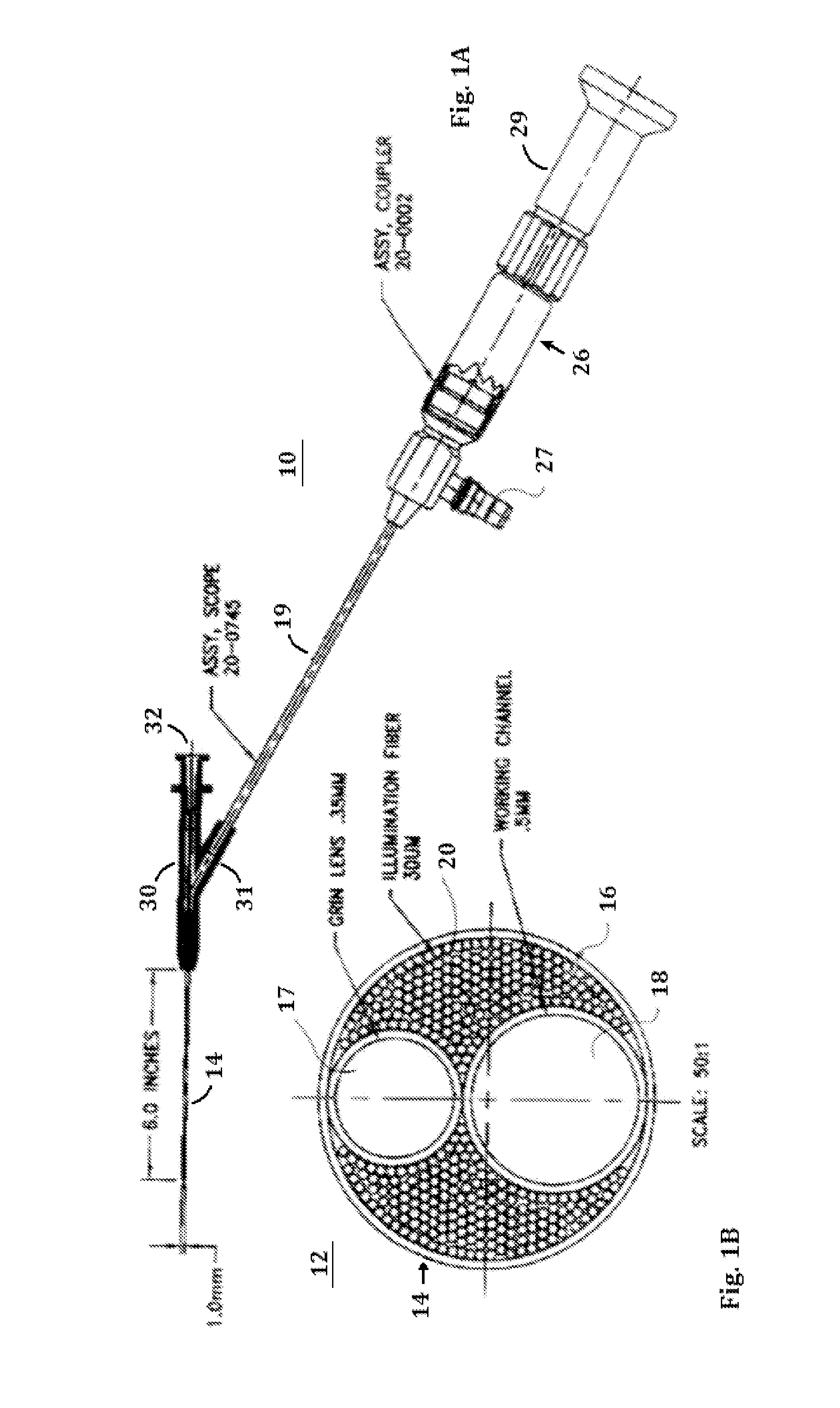
[0035]A microendoscope assembly as outlined in FIGS. 1A-1B was developed and tested. Results of the testing are summarized below.

[0036]I) IMAGE SIZE: Increased significantly over earlier Generations. (68% screen coverage of a 19″ monitor was routinely produced.)

[0037]II) IMAGE QUALITY: An 8″ screen image consistently yielded great quality clarity, color and depth of field.

[0038]III) CONTINUOUS IMAGING: Constant real-time video imaging was maintained continuously without distortion.

[0039]IV) MANEUVERABILITY FACTOR: Highly flexible shaft allowed significantly increased “corner turning” ability and mobility around obstacles.

[0040]V) IMMERSION FUNCTIONALITY: Scope performed under liquids of varying density, maintaining benchmark image quality through the water whether standing, swirling or other turbulence.


PUM


Abstract

The present invention generally relates to a microendoscope assembly capable of intra-ductal use. The microendoscope generally comprises: an outer cylindrical guide tube defining an internal passageway having an exterior diameter of no greater than about 1.0 mm; a first internal cylindrical tube defining a working channel having an interior diameter of no less than about 0.5 mm; a second internal cylindrical tube defining a image guide and housing a lens; and an illumination bundle comprising optic fibers.

Description

FIELD OF THE INVENTION[0001]The present invention is generally directed toward a microendoscope and methods of use thereof.BACKGROUND OF THE INVENTION[0002]In recent years there has been increasing use of endoscopes for minimally invasive treatment and diagnosis. For example, endoscopes have attempted to be used in diagnostic procedures, e.g., in sinus cavities, breast tissues, and other small diameter ducts. However, current endoscope designs are limited in the small spaces required.[0003]Breast cancer is the second most common malignancy among women. In the United States alone: (a) one person dies from breast cancer every 14 minutes; (b) 250,000 cases of breast cancer are confirmed annually: (c) there is a lifetime risk that one in eight women will have cancer in their lifetime; (d) it is estimated that 2.6 million women have breast cancer; (e) 75% of breast cancers occur in women over 50 years of age; (f) breast cancer is the most common malignancy among women; (g) 40 million mam...

Claims


Application Information

Patent Timeline
Patent Type & Authority Applications(United States)
IPC IPC(8): A61B10/04A61B1/00A61B1/07A61B1/018
CPCA61B1/00165A61B1/313A61B1/018
Inventor WORTH, HOWARDWALKER, DAVID
Owner LUMINUS VENTURES
Why Eureka
Try Eureka