
Transconnector

a technology of transconnector and connector, which is applied in the field of transconnector, can solve the problems of providing surgeons with one or more difficulties

Active Publication Date: 2010-08-12
SYNTHES USA
View PDF26 Cites 61 Cited by
  • Summary
  • Abstract
  • Description
  • Claims
  • Application Information

AI Technical Summary

Benefits of technology

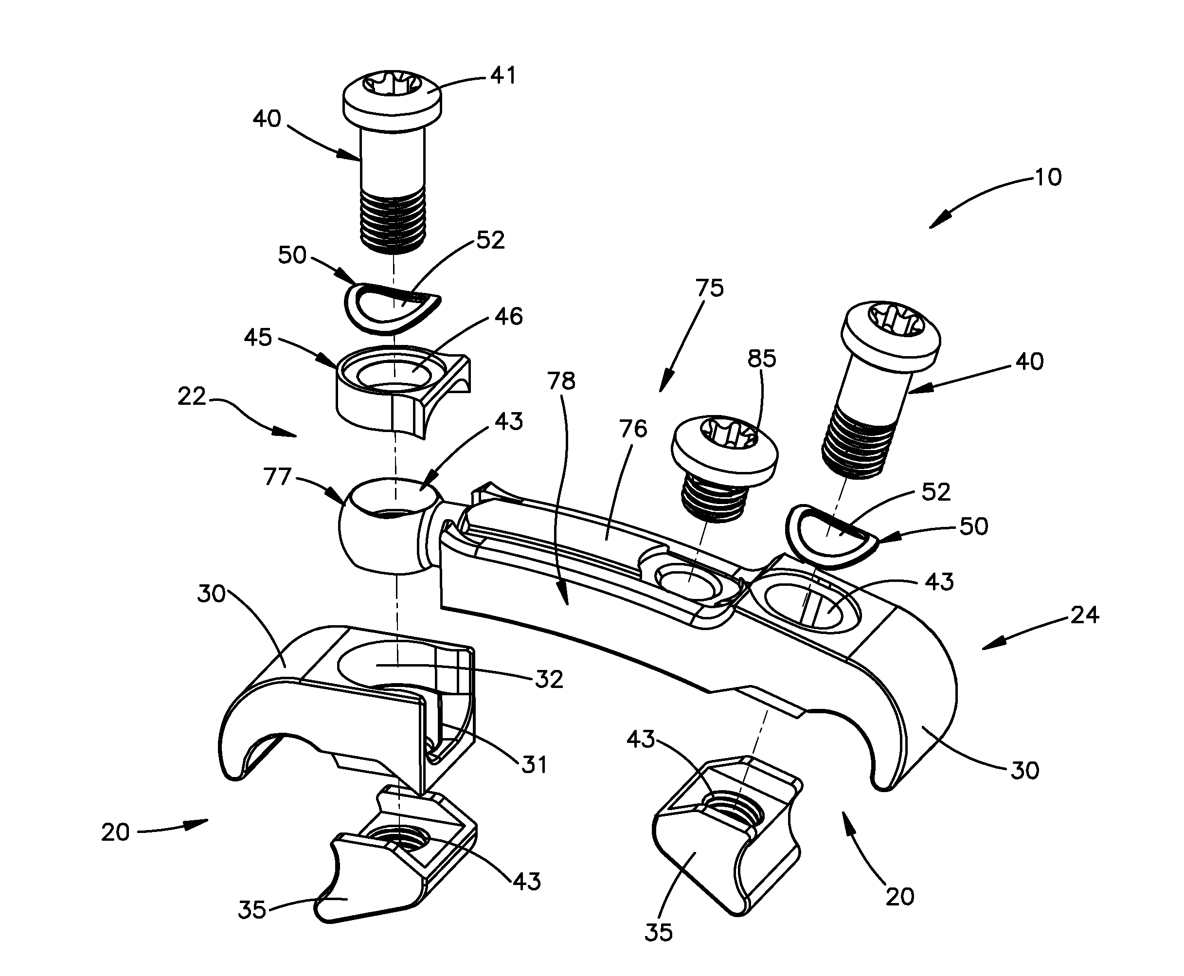
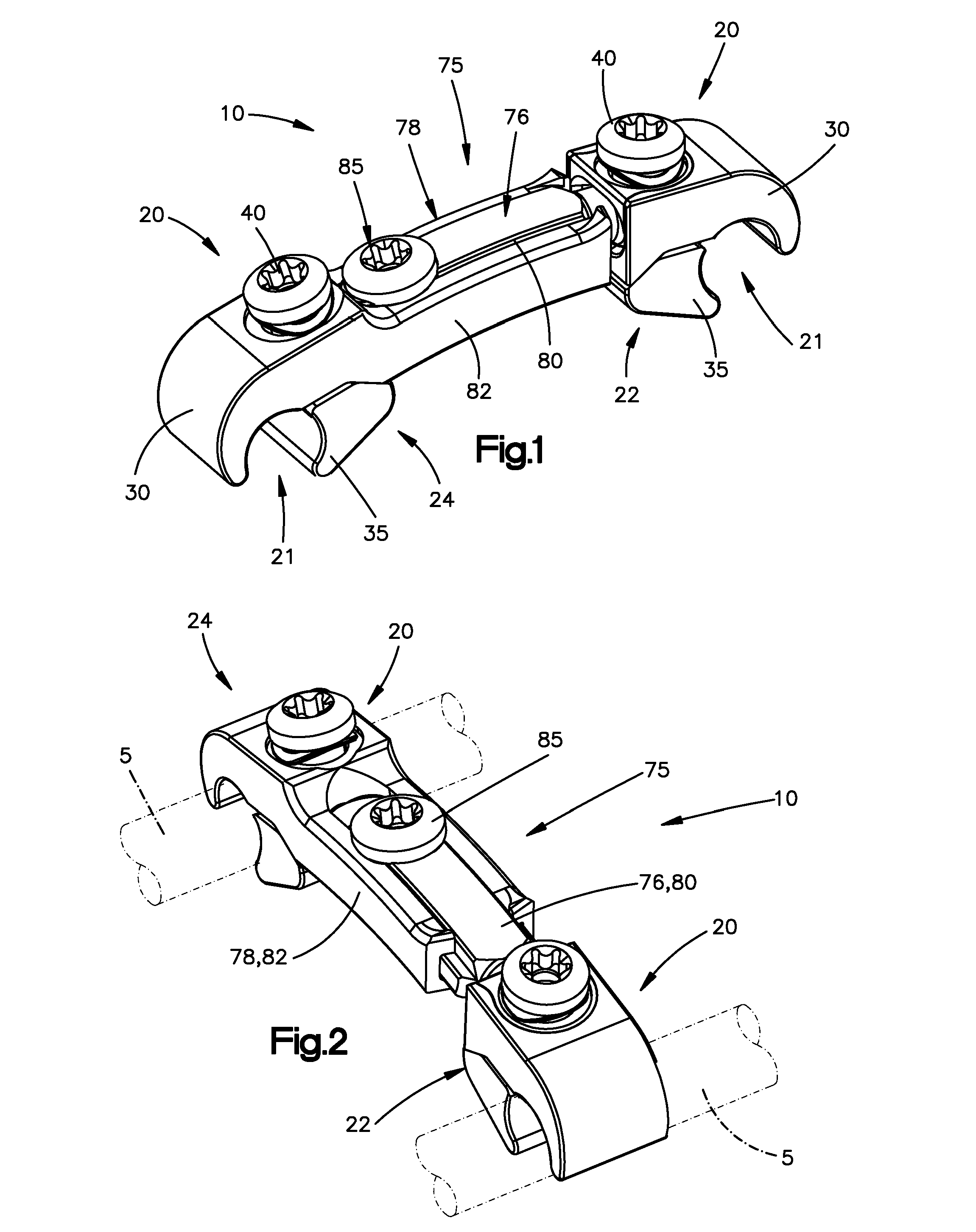
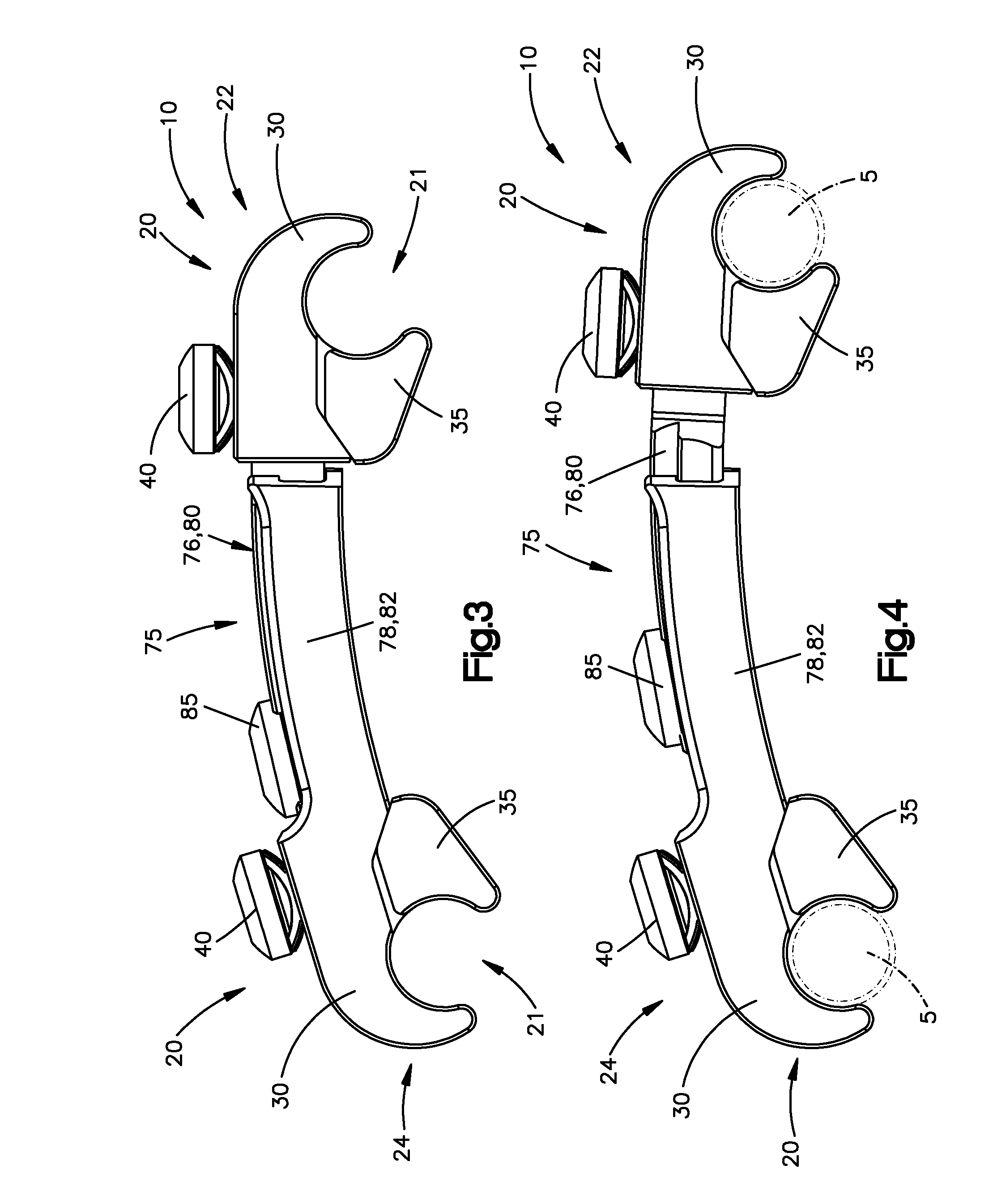
[0010]In one exemplary embodiment, the transconnector may include a bridge member having first and second ends and first and second rod engaging members. The first rod engaging member is coupled to the first end of the bridge member while the second rod engaging member is coupled to the second end of the bridge member. The first and second rod engaging members each include a rod receiving channel for receiving first and second rods, respectively. At least the first rod engaging member being able to articulate with respect to the bridge member. The first rod engaging member including an upper clamp body, a lower clamp body, an actuation screw, a compression cap and a spring. The first end of the bridge member including a bore for receiving the actuation screw such that the actuation screw passes through the spring, the compression cap, the upper clamp body, the first end of the bridge member and into threaded engagement with the lower clamp body such that rotation of the actuation screw moves the lower clamp body with respect to the upper clamp body to thereby secure the rod within the rod receiving channel and to secure the position of the first rod engaging member with respect to the bridge member. The spring biasing the lower clamp body into engagement with the upper clamp body so that the first rod engaging member can provisionally snap onto the rod received within the rod receiving channel.

Problems solved by technology

The use of transconnectors, however, can provide surgeons with one or more difficulties.
However, due to a wide variety of factors, the two spinal rods are rarely geometrically aligned in this manner in clinical situations.
The addition of such adjustability, however, may require the transconnector to include numerous pieces that can be difficult to assemble and use while in the surgical environment.

Method used


Image

  • Transconnector
  • Transconnector
  • Transconnector

Examples


Embodiment Construction

[0029]Certain terminology is used in the following description for convenience only and is not limiting. The words “right”, “left”, “top” and “bottom” designate directions in the drawings to which reference is made. The words “inwardly” and “outwardly” refer to directions toward and away from, respectively, the geometric center of the device and designated parts thereof. The words, “anterior”, “posterior”, “superior”, “inferior” and related words and / or phrases designate preferred positions and orientations in the human body to which reference is made and are not meant to be limiting. The terminology includes the above-listed words, derivatives thereof and words of similar import.

[0030]Referring to FIGS. 1-13, certain exemplary embodiments will now be described with reference to the drawings, wherein like reference numerals are used to refer to like elements throughout. In general, such embodiments relate to cross-braces or transconnectors 10, 10′, 200, 300, 400 (collectively referr...


PUM


Abstract

A transconnector for use in interconnecting a pair of longitudinal spinal rods in a spinal fixation procedure. The transconnector includes a bridge member and first and second spinal rod engaging members. The bridge member may include first and second members, wherein the first and second members are moveably associated with one another so that the distance between the first and second spinal rod engaging members can be adjusted. The first and second spinal rod engaging members include a rod receiving channel for receiving one of the spinal rods therein. The spinal rod engaging members may be articulating in, for example, the yaw and roll positions or non articulating with respect to the bridge members. The spinal rod engaging members preferably include a spring, for example, a spring washer, to provide an opposing force so that the spinal rod engaging members can provisionally snap onto the spinal rods.

Description

CROSS REFERENCE TO RELATED APPLICATIONS[0001]This application claims priority to U.S. provisional patent application Ser. No. 60 / 975,071, filed Sep. 25, 2007, the content of which is hereby incorporated by reference in its entirety.FIELD OF THE INVENTION[0002]The present invention relates to a device for spinal fixation, and in particular to a transconnector for coupling longitudinal spinal rods, or other elongated members.BACKGROUND OF THE INVENTION[0003]Spinal fusion is a procedure that involves joining two or more adjacent vertebrae with a spinal fixation device to restrict movement of vertebrae with respect to one another. For a number of known reasons, spinal fixation devices are used in spine surgery to align and / or fix a desired relationship between adjacent vertebrae. Such devices typically include a pair of spinal fixation devices, such as, for example, a longitudinally spinal rod, a plate, etc., longitudinally placed on the posterior spine on either side of the spinous pro...

Claims


Application Information

Patent Timeline
IPC IPC(8): A61B17/70
CPCA61B17/705A61B17/88A61B17/7049A61B17/7052
Inventor RATHBUN, DAVID S.BANOWETZ, JASONEAMES, HEATHER
Owner SYNTHES USA
Learn More