

Attachment system of photovoltaic cell to fluoropolymer structural membrane
a technology of fluoropolymer and structural membrane, applied in the direction of photovoltaic supports, heat collector mounting/support, light and heating apparatus, etc., can solve the problem that the photovoltaic device remains relatively non-extensible, and achieve the effect of less flexibl
- Summary
- Abstract
- Description
- Claims
- Application Information
AI Technical Summary
Benefits of technology
Problems solved by technology
Method used
Image

Examples
example 1
[0222]Construction of a Photovoltaic Device / Architectural Membrane on Site Field
[0223]Ensure that the area of architectural membrane (20) (SHEERFILL® II HT) to be bonded is clean and dry.
[0224]A piece of bondable, one side unencapsulated fabric (30) (SHEERFILL® M26 OS) would be cut slightly larger than the plan pattern of the Velcro (50).
[0225]For example, a piece of 5 mil FEP film (NORTON® FEP) (80) would be cut slightly larger than the plan pattern of one side fabric (30).
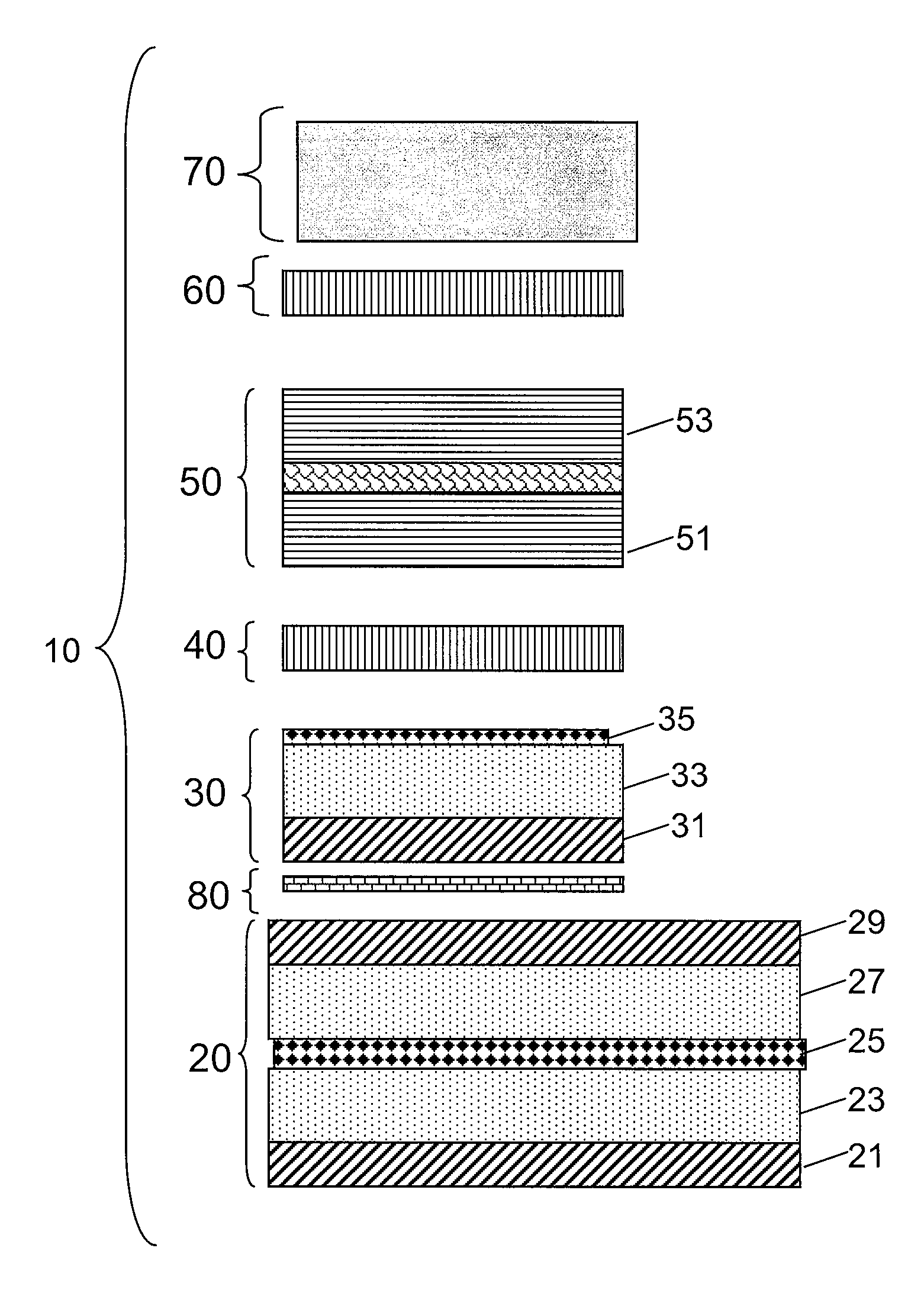
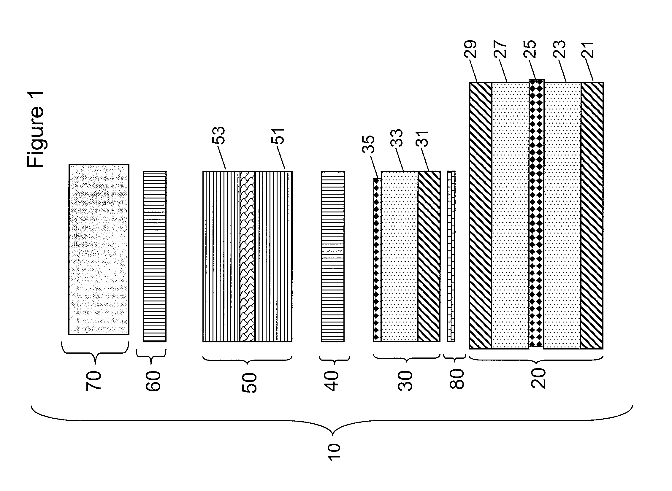
[0226]The three layers would be laid up in the desired pattern in the order shown in FIG. 1. The orientation of the one side fabric (30) would be such that the bondable layer (31) is facing the 5 mil FEP (80).
[0227]Heat and pressure would be applied for a period of time adequate to melt and flow the FEP (700° F., 4 psi, 3 minutes). A heated platen on the outer side of the combined layers could be used. A release membrane (such as silicone paper or Kapton®) could be used to cover the platen surface during heating....
example 2
Construction of a Photovoltaic Device / Architectural Membrane in a Fabrication Facility
[0233]Formation of the Lower Half of the Construction:
[0234]The area of architectural membrane (20)(SHEERFILL® II HT) to be bonded was clean, dry and tensioned.
[0235]A piece of bondable, one side unencapsulated fabric (30) (SHEERFILL® M26 OS) was cut slightly larger than the plan pattern of the Velcro (50).
[0236]A piece of 3 mil FEP film (NORTON® FEP) (80) was cut slightly larger than the plan pattern of one side fabric (30).
[0237]The three layers were laid up in the desired pattern in the order shown in FIG. 1. The orientation of the one side fabric (30) was such that the bondable layer (31) was facing the 5 mil FEP (80).
[0238]Heat and pressure were applied for a period of time adequate to melt and flow the FEP (700° F., 4 psi, 3 minutes). Heated platens on either side of the combined layers were used. Release membranes (such as silicone paper or Kapton®) were used to cover the surfaces of the pla...
example 3
[0248]The following provides a stepwise method of preparing, for example, an embodiment as depicted in FIGS. 3 and 4.
[0249]3001 loop 53 Velcro was attached to a Unisolar flexible module 70 with an adhesive 60 (Firestone butyl adhesive tape). One option provided with the Unisolar flexible module 70 is the availability of receiving it with butyl adhesive 60 on the back side. Alternatively, an adhesive 60 can be applied to the back side of the module.
[0250]The photovoltaic module 70 was placed with butyl adhesive 60 side up, the release paper removed, the loop material 53 (cut to size) was rolled over the butyl adhesive 60 and embedded in the butyl adhesive 60 by applying pressure to the loop 53 with a 10 pound roller.
[0251]A frame of Velcro type 752 hook material 51 was prepared. Alternatively, straight portions of hook material 51 were cut and formed into a 4 inch frame around the perimeter.
[0252]The hook material 51 was embedded into the loop material 53 by applying pressure / rolling...
PUM
| Property | Measurement | Unit |
|---|---|---|
| Flexibility | aaaaa | aaaaa |
| Adhesivity | aaaaa | aaaaa |
| Perimeter | aaaaa | aaaaa |
Abstract
Description
Claims
Application Information