Compression screw assembly, an orthopedic fixation system including a compression screw assembly and method of use

a screw and compression screw technology, applied in the field of compression screw assembly and orthopedic fixation system, can solve the problems of bone trauma, weakened interfragmental compression, uncontrollable compression screw assembly,

Inactive Publication Date: 2010-08-19
EXTREMITY MEDICAL
View PDF8 Cites 61 Cited by
  • Summary
  • Abstract
  • Description
  • Claims
  • Application Information

AI Technical Summary

Benefits of technology

[0013]Another object of the invention is to provide a compression screw driver assembly that is utilized to provide a controlled application of compression during insertion of the compression screw assembly into bone.

Problems solved by technology

However, this compression screw assembly is uncontrollable because there is no limit or control on the amount of compression applied to the bone fragments.
As the threads on the screw shank oppose the compression applied by the screw head when the two-pieces are rotated within the bone fragments, interfragmental compression is weakened.
In addition, the screw head may torque beyond the limits that the bone fragment can handle, causing bone trauma and affecting the proper healing of the fracture.

Method used


Image

  • Compression screw assembly, an orthopedic fixation system including a compression screw assembly and method of use
  • Compression screw assembly, an orthopedic fixation system including a compression screw assembly and method of use
  • Compression screw assembly, an orthopedic fixation system including a compression screw assembly and method of use

Examples


Embodiment Construction

[0037]The invention may be understood more readily by reference to the following detailed description of preferred embodiment of the invention. However, techniques, systems and operating structures in accordance with the invention may be embodied in a wide variety of forms and modes, some of which may be different from those in the disclosed embodiment. Consequently, the specific structural and functional details disclosed herein are merely representative, yet in that regard, they are deemed to afford the best embodiment for purposes of disclosure and to provide a basis for the claims herein, which define the scope of the invention. It must be noted that, as used in the specification and the appended claims, the singular forms “a”, “an”, and “the” include plural referents unless the context clearly indicates otherwise.

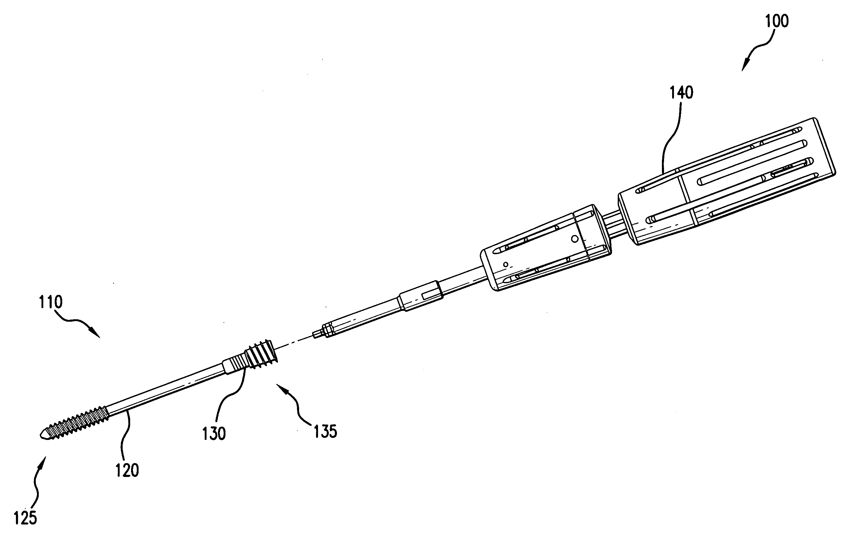
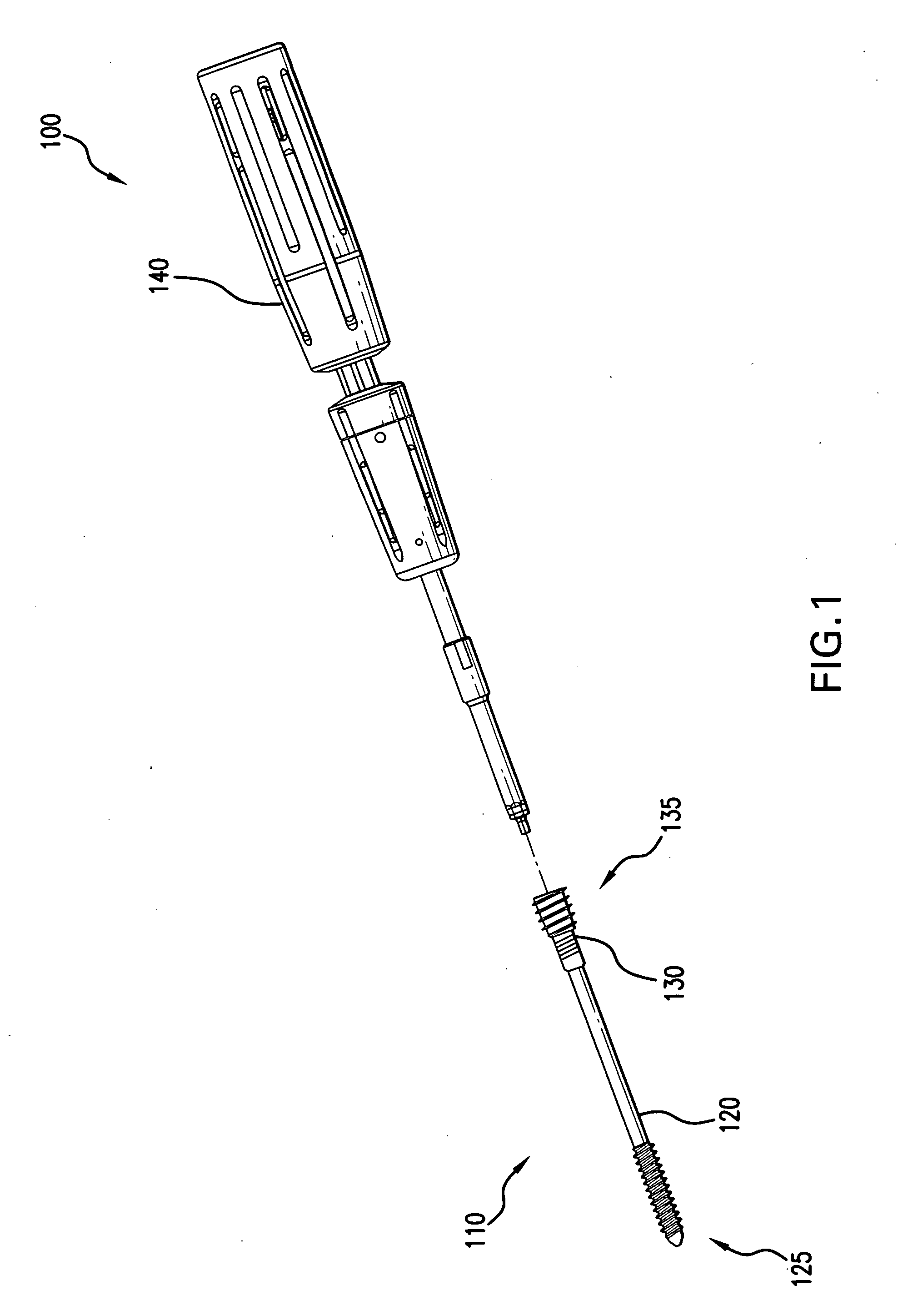
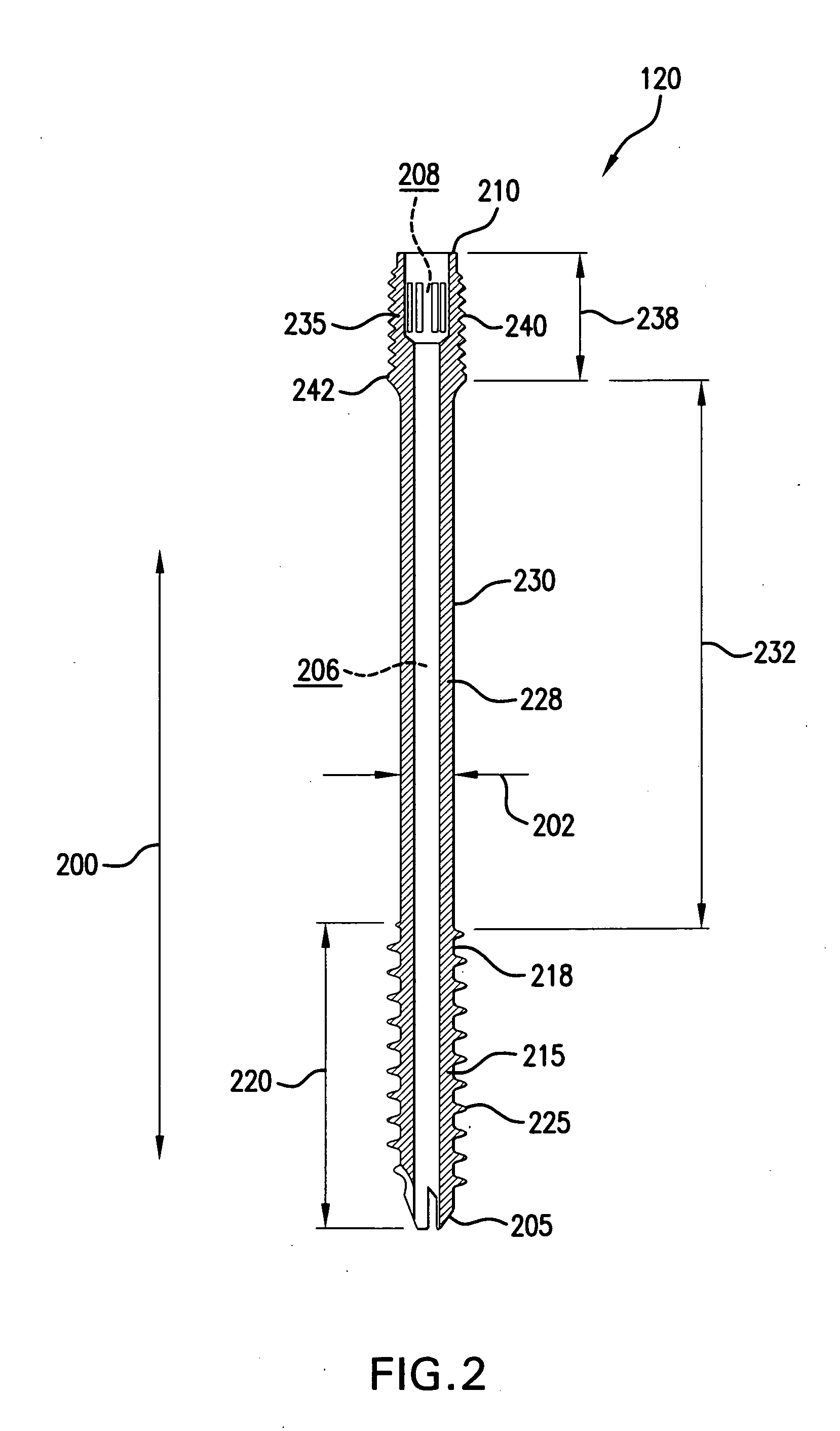
[0038]Referring now to FIG. 1, there is shown an orthopedic fixation system 100 which is made in accordance with the teachings of the preferred embodiment of the inven...


PUM


Abstract

A compression screw assembly includes a first primary member having a threaded leading portion of a first pitch, a smooth middle portion and a threaded trailing portion of a second pitch with the trailing portion residing directly opposite leading portion. The compression screw assembly includes a second threaded screw head member positioned at a distal end having external threads, which are of the same pitch as the plurality of threads of the leading portion, and internal threads of a fourth pitch and dissimilar screw leads from the external threads. The difference in screw leads causes the compression screw member to apply a compressive force on bone fragments when compression screw assembly is inserted into bone fragments.

Description

FIELD OF THE INVENTION[0001]This invention relates to the field of orthopedic implant devices, and more particularly, to a compression screw assembly, an orthopedic fixation system and a method of utilizing the compression screw assembly to provide a compressive force to secure two or more bone fragments or bones together.BACKGROUND OF THE INVENTION[0002]Orthopedic fixation systems, which include orthopedic implant devices are often used to repair or reconstruct bones and joints, and to repair bone fractures, degenerative bone conditions and similar types of injuries.[0003]Frequently, these systems require that bone fragments, such as cracked, broken, or osteotomy bones be kept attached together for lengthy periods of time under a sustained force across the fractured site in order to promote healing. As such, these systems serve to apply interfragmental compression to bone fragments as well as to realign bone segments and to restore native geometries.[0004]The orthopedic implant dev...

Claims


Application Information

Patent Timeline
Patent Type & Authority Applications(United States)
IPC IPC(8): A61B17/86A61B17/58
CPCA61B17/863A61B17/8875A61B17/8872
Inventor TYBER, JEFFJAMY, GANNOE
Owner EXTREMITY MEDICAL
Why Eureka
Try Eureka