Production and use of laminated nanofibrous structures

a nanofibrous and nanotechnology, applied in the field of nanofibrous structure production and use, can solve the problems of inability to obtain the large surface area required for many applications in an economic feasible way, increased amount of bleaching agent provided, system leakage of bleaching agent to gingiva, optional ingestion, etc., to achieve good control release and filtration properties, good overlap, good liquid uptake

Inactive Publication Date: 2010-08-26
UNIV GENT
View PDF7 Cites 16 Cited by
  • Summary
  • Abstract
  • Description
  • Claims
  • Application Information

AI Technical Summary

Benefits of technology

[0011]It is an object of the present invention to provide innovative devices or methods for producing fibrous (e.g. nanofibrous) structures. It is an advantage of embodiments according to the present invention that fibrous structures comprising fibres, wherein the diameter of the fibres varies, e.g. decreases, along a dimension of the electrospun fibrous structure can be obtained and methods and apparatus for producing them. It is an advantage of embodiments according to the present invention that methods and systems are provided resulting in nanofibrous structures with a firm structure, i.e. nanofibrous structures that are little or not subject to decomposition, distortion or delamination in normal use. It is an advantage of embodiments according to the present invention that methods and systems are provided resulting in strong, porous and / or reproducible nanofibrous structures. It is furthermore an advantage of embodiments according to the present invention that fibrous structures with good liquid uptake are provided and methods for producing them. It is also an advantage of embodiments according to the present invention that fibrous structures with good control release and filtration properties are provided and methods for producing them. It is an advantage of embodiments according to the present invention that fibrous structures can be provided in an economic viable way. It is an advantage of embodiments according to the present invention that fibrous structures with a combination of two or more of the above described advantages can be obtained. It is an advantage of embodiments according to the present invention that laminated structures can be made. It is an advantage of embodiments according to the present invention that a good overlap is obtained using movement of the different nozzles with respect to the collector.

Problems solved by technology

In addition, application of nanofibrous structures in filtration requires a strong structure with high dirt holding capacity, multilevel filtration, low cut-off value and limited pressure drop.
Therefore, with a single nozzle system, it is not possible to obtain the large surface areas required for many applications in an economic feasible way.
Especially in the case of burn wounds, it is a major issue to deal with wound exudates produced by the wound.
As these systems often do not result in a perfect fit to the teeth, the amount of bleaching agent provided often is increased.
On the other hand, such systems also suffer from leakage of the bleaching agent to the Gingiva and optionally to ingestion.

Method used


Image

  • Production and use of laminated nanofibrous structures
  • Production and use of laminated nanofibrous structures
  • Production and use of laminated nanofibrous structures

Examples


example 1

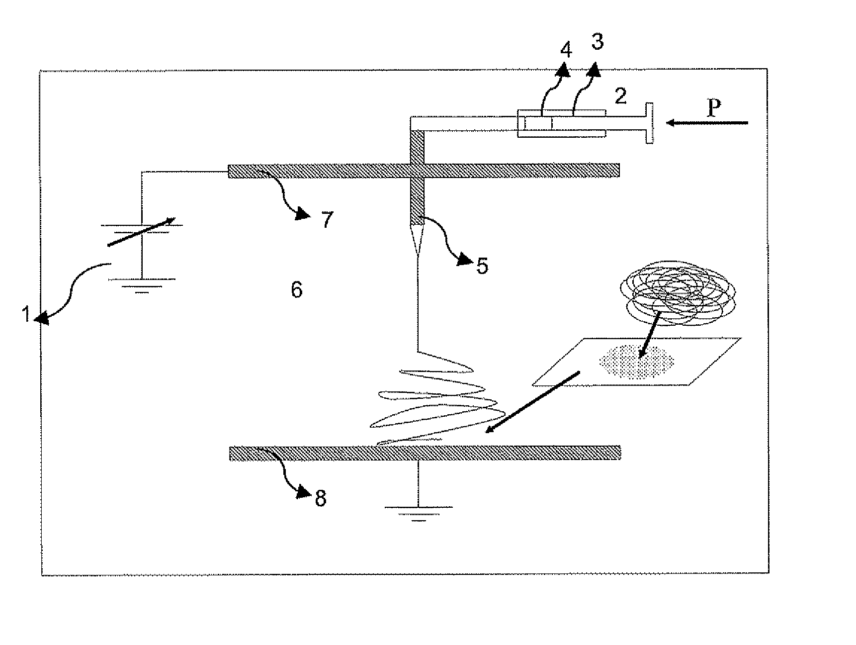
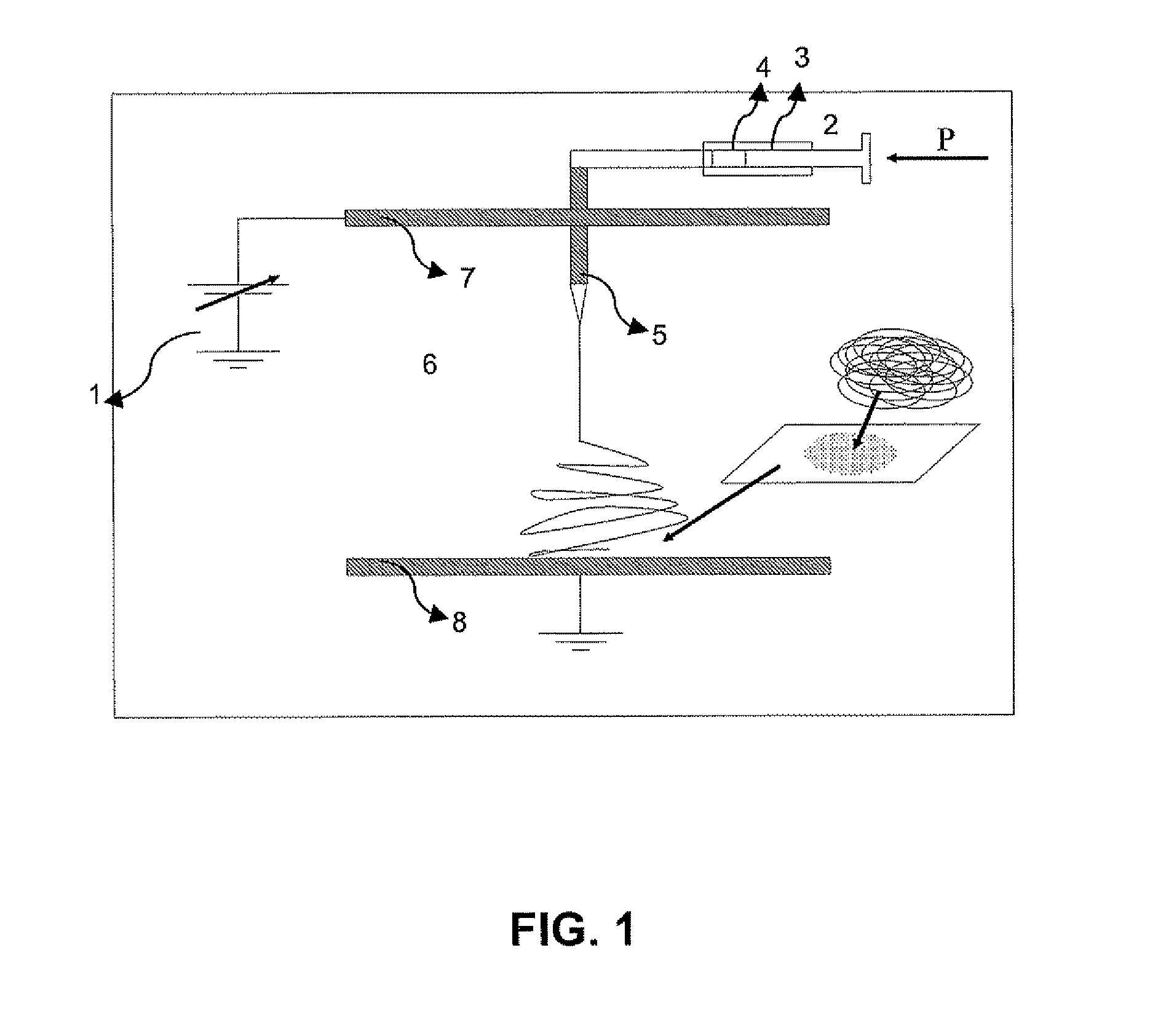
[0225]Polyester amide (PEA), obtained through synthesis from fatty acids, with molecular weight of about 20.000 g mol−1 was dissolved in chloroform to obtain a solution of 25% PEA. The solution was pumped to a set of 24 outlets with a multitude of multichannel peristaltic pumps, using a flow rate of 15 mL h−1 per outlet. In the spinneret an electrical field of about 1000 V cm−1 is applied over the outlets and the receiving surface in order to allow electrospinning of the polymer solution. The outlets were positioned in the triangle configuration of 4 rows of 6 outlets per row. Temperature control was performed at 298 K. The outlet surface was positioned under an angle of 10° relative to the receiving surface and the outlet surface moved perpendicular to the movement of the receiving surface. The speed of the receiving surface was 40 cm h−1, while the rate for the outlet surface is 1 cm s−1. After 2 hours of spinning a nanofibrous structure of 300 μm thick was obtained with a length ...

example 2

[0226]Poly amide 6 / 6 (PA66) with molecular weight of about 20.000 g mol−1 was dissolved in formic acid to obtain a solution of 14% PA66. The solution was pumped to 2 sets of each 24 outlets with a multitude of multichannel peristaltic pumps, using a flow rate of 2 mL h−1 per outlet. In the spinneret an electrical field of about 3.500 V cm−1 was applied over the outlets and the receiving surface in order to allow electrospinning of the polymer solution. The outlets were positioned in the triangle configuration of 4 rows of 6 outlets per row. Two spinnerets were used, each operational at a different distance between the outlets and the receiving surface. Temperature control was performed at 298 K. The first outlet surface was positioned at a distance of 4 cm, while the second was positioned at a distance of 6 cm from the receiving surface. The speed of the receiving surface was 60 cm h−1, while the rate for the outlet surface is 1 cm s−1. After 2 hours of spinning a nanofibrous struct...

example 3

[0228]Cellulose acetate (CA) with molecular weight of about 30.000 g mol−1 was dissolved in acetone / Dimetylacetamide 2:1 to obtain a solution of 14% CA. The solution was pumped to 2 sets of each 24 outlets with a multitude of multichannel peristaltic pumps, using a flow rate of 10 mL h−1 per outlet. In the spinneret an electrical field of about 850 V cm−1 was applied over the outlets and the receiving surface in order to allow electrospinning of the polymer solution. The outlets were positioned in the triangle configuration of 4 rows of 6 outlets per row. Two spinnerets were used, each operational at a different distance between the outlets and the receiving surface. Temperature control was performed at 298 K. The first outlet surface was positioned at a distance of 20 cm, while the second was positioned at a distance of 15 cm from the receiving surface. The speed of the receiving surface was 60 cm h−1, while the rate for the outlet surface was 1 cm s−1. After 2 hours of spinning a ...


PUM

PropertyMeasurementUnit
distanceaaaaaaaaaa
distanceaaaaaaaaaa
diameteraaaaaaaaaa

Abstract

An electrospinning device is described for producing fibrous porous structures. The device is adapted for providing a predetermined distance profile for the distance between outlets of the electrospinning device and the receiving surface. The latter may be obtained by geometrically adapting the electrospinning device or by moving the outlets with respect to the receiving surface during growth of the fibrous structure. A fibrous structure obtained by the described electrospinning device is also described which comprises fibres, wherein the diameter of the fibres has a predetermined profile along a dimension of the electrospun fibrous structure. Furthermore application of the laminated structure for wound dressing and teeth bleaching is discussed.

Description

TECHNICAL FIELD OF THE INVENTION [0001]The present invention relates to a fibrous structure, a process and a device for manufacturing the same. In particular, the present invention relates to methods and systems for electrospinning of fibrous structures and resulting products such as e.g. nanofibrous structures and their use. The present invention also relates to the field of wound dressing. More particularly, the present invention relates to methods and systems for controlling an amount of liquid near a surface, such as for example in wound dressing applications. The present invention also relates to the field of dental applications. More particularly, the present application relates to methods, products and systems for whitening of teeth applications.BACKGROUND OF THE INVENTION[0002]Nanofibrous structures are useful in a variety of applications in the fields of clothing, filtering, medicine and defence. There is a strong interest in nanofibrous structures based on their high poros...

Claims


Application Information

Patent Timeline
Patent Type & Authority Applications(United States)
IPC IPC(8): B32B5/02B29C47/08A61C17/00B29C48/345D04H1/728D04H3/16
CPCD01D5/0061D04H3/16D04H1/728D01D5/247Y10T428/249924
Inventor WESTBROEK, PHILIPPEVAN CAMP, TAMARADE VRIEZE, SANDERDE CLERCK, KAREN
Owner UNIV GENT
Why Eureka
Try Eureka