
Field replaceable unit for solid state drive system

a solid-state drive and field replacement technology, applied in the field of removable modules, can solve problems such as disruptive maintenance of ssd systems

Inactive Publication Date: 2010-08-26
SUN MICROSYSTEMS INC
View PDF27 Cites 27 Cited by
  • Summary
  • Abstract
  • Description
  • Claims
  • Application Information

AI Technical Summary

Problems solved by technology

Some SSD systems are subject to disruptive maintenance in that component service performed in the field requires the powering down of the system to access failed components within the system enclosure.

Method used


Image

  • Field replaceable unit for solid state drive system
  • Field replaceable unit for solid state drive system
  • Field replaceable unit for solid state drive system

Examples


Embodiment Construction

)

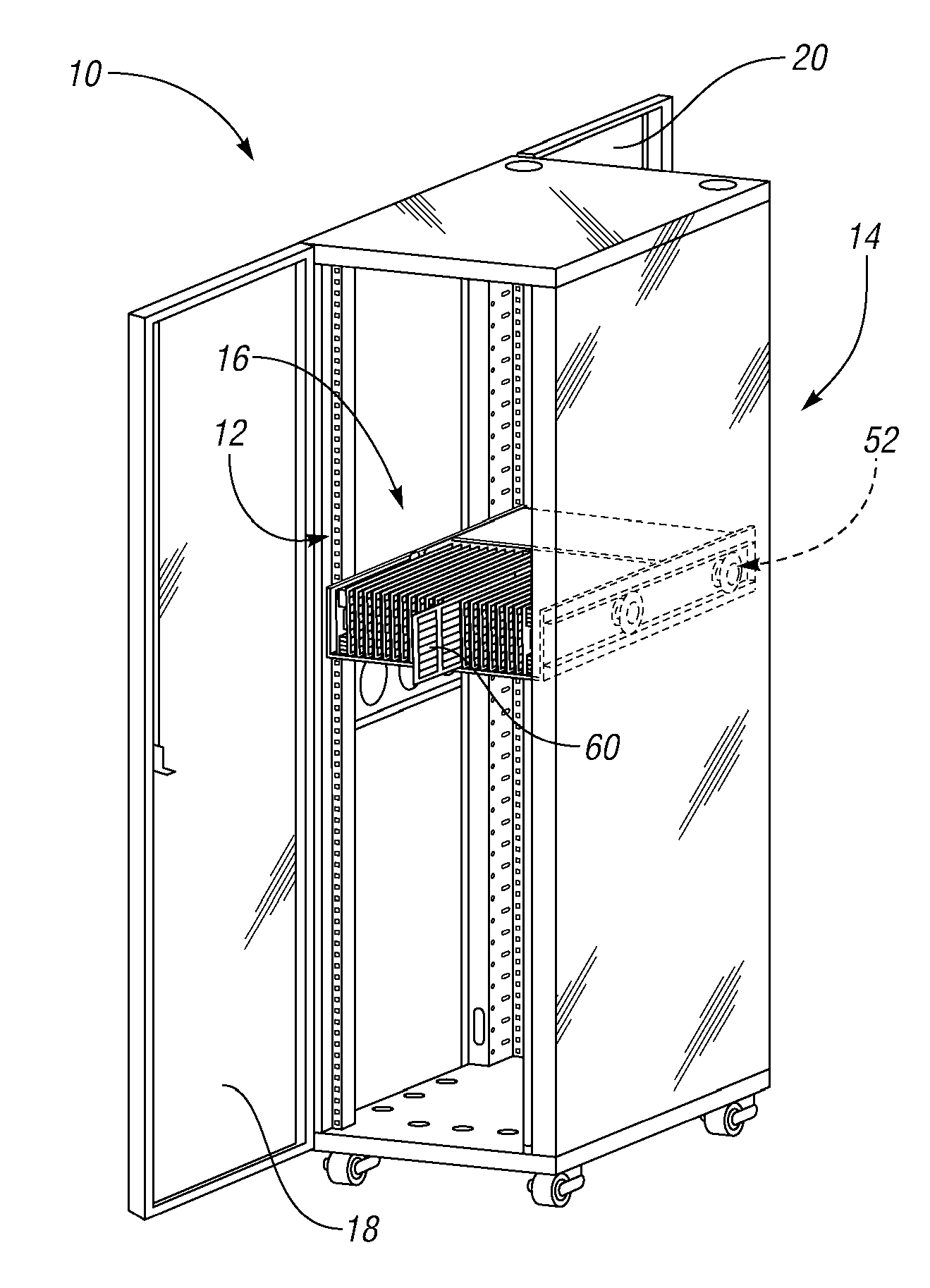
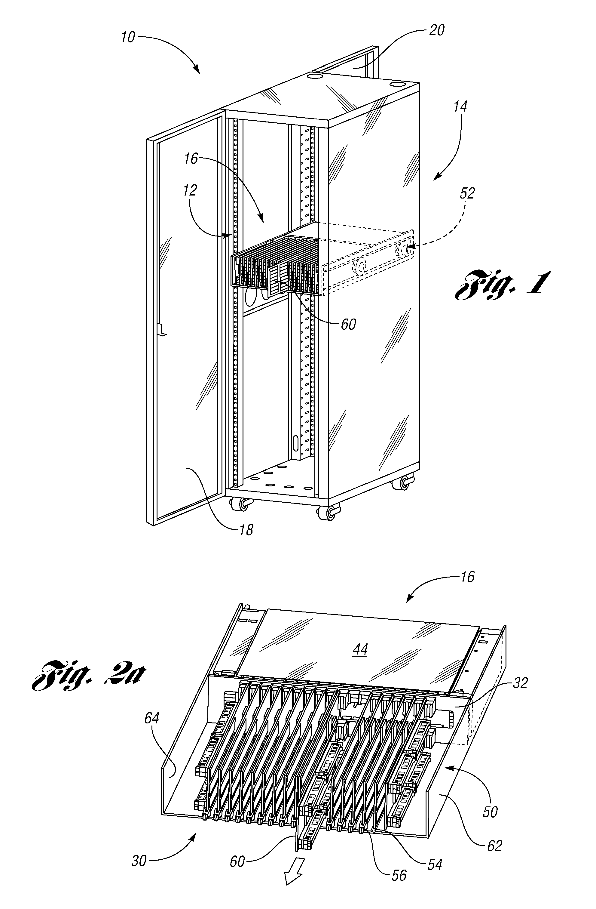
[0011]FIG. 1 illustrates a solid state drive system (SSD) 10 in accordance with one non-limiting aspect of the present invention. The SSD system 10 may include a number of racks 12 disposed within an interior of a housing 14 to hold a number of SSD units 16. The SSD unit 16 may include a number of SSD and non-SSD components to support any number of operations, such as but not limited to those commonly used to support data storage systems, servers, and other computing centers. While only the one unit 16 is shown to be loaded within a rack 12, any number of units may be loaded into the housing 14.

[0012]The housing 14 may be constructed out of metal or plastic and include four fixed side walls and front 18 and rear access panels 20. The access panels 18, 20 may be hinged to the side walls or otherwise removable to permit access to the unit 16. Electrical power and signal connections to the unit may be made through a bus or other wiring included within the housing 14. Optionally, the r...


PUM


Abstract

A unit for use as a solid state drive (SSD) system. The unit may include a number of removable components that can be field serviced without having to replace the entire unit and without having to remove the unit from its operational rack support structure.

Description

BACKGROUND OF THE INVENTION[0001]1. Field of the Invention[0002]The present invention relates to removable modules of the type used within solid state drive (SSD) systems.[0003]2. Background Art[0004]With the explosion of data that needs to be processed efficiently and immediately accessible, companies of all sizes are looking to open source storage solutions that work with general purpose hardware. Flash-based innovations, commonly referred to as solid state drive (SSD) innovations, enable customers to immediately increase application performance and save on energy costs compared to traditional Fibre Channel hard drives. SSD technology can enable greater system utilization and scalability that will decrease server and storage sprawl in already maxed-out data centers.[0005]Some SSD systems are subject to disruptive maintenance in that component service performed in the field requires the powering down of the system to access failed components within the system enclosure. These types...

Claims


Application Information

Patent Timeline
IPC IPC(8): G06F13/00
CPCG06F13/409G06F1/188
Inventor PAVOL, ERIC G.RHOAD, DAVID M.
Owner SUN MICROSYSTEMS INC
Learn More