Apparatus and method for variably sterilizing aqueous liquids

a technology of aqueous liquid and apparatus, which is applied in the direction of moving filter element filters, separation processes, filtration separation, etc., can solve the problems of ineffective use of light, inconvenient use, and inability to sterilize aqueous liquid, so as to achieve safe and efficacious decontamination of aqueous liquids

Active Publication Date: 2010-09-02
ALDRIDGE PABLO +1
View PDF2 Cites 3 Cited by
  • Summary
  • Abstract
  • Description
  • Claims
  • Application Information

AI Technical Summary

Benefits of technology

[0012]In brief summary, this novel invention alleviates all of the known problems related to safely and efficaciously decontaminating aqueous liquids for a variety of uses. The invention is a “flow-through” device which receives influent contaminated liquid or impure liquid of questionable pollution and provides a sterilized effluent product decontaminated to meet a variety of applications. Further, sterilization levels (i.e. SALs) may be facilely, accurately, predictively and variably controlled, depending upon known or assumed characteristics of an influent liquid to be sterilized and projected use of that liquid. Sterilization to various levels is realized through changing but a single variable (flow rate through the apparatus) and while other parameters, such as heating temperature, pressure, etc., are kept substantially constant.
[0019]The second valve may selectively be gated by an “AND” combination of water temperature and pressure sensors, although a temperature regulated valve in series with the first valve also performs the “AND” function. The temperature and pressure sensors are each disposed at individual predetermined strategic sites within the water flow path. In one embodiment, temperature is sensed by a bi-metallic sensor switch disposed within the reservoir, sufficiently close to the influent site of the reservoir to assure that a predetermined minimum sterilization temperature has been achieved, thereby assuring maintenance of the minimum sterilization temperature within the remainder of the reservoir. In this embodiment, a pressure sensor, having a pressure-sensitive switch, is disposed downstream from the reservoir. The pressure sensor is selectively closed when a predetermined sterilization upstream pressure is detected. The contacts of the temperature sensor and pressure sensor are connected in series such that when contacts of each switch close the second valve is opened (i.e. before the second valve opens, the temperature sensor must sense at least a predetermined temperature and the pressure sensor, likewise, must have detected a predetermined pressure.) Importantly, simultaneously meeting these combined conditions assures achieving target SAL in the effluent, thereby protecting sterility of the downstream system.
[0020]Also, each switch of each sensor is opened and closed at different values (of temperature and pressure), thereby creating a hysteresis in each switching parameter and, as a result, assuring stable operation. For example, the temperature sensor may operate to close the temperature switch at a temperature of substantially 150° C. and operate to open the switch at 140° C. In tandem with the temperature sensor, the pressure sensor may operate to close the pressure switch at 50 psi and open the pressure switch at 40 psi. In the case of the “AND” gate, only when both switches are closed is the second valve opened.
[0023]It is a fundamental object to provide an aqueous liquid purification system which controllably sterilizes an aqueous liquid to a predetermined SAL by controlling rate of flow of the aqueous liquid through said system.
[0027]It is an object to provide an energy efficient system which transfers thermal energy from effluent liquid, after sterilization, to influent liquid before sterilization, thereby reducing effluent temperature to a predetermined lower temperature level before leaving the system and preheats influent aqueous liquid before it enters the heating unit.

Problems solved by technology

With these statistics, it is astounding that no water purification method is currently available and in-use to prevent such water borne illnesses.
Likely such is not available due expense of currently available water purification systems.
However, use of light is known to sometimes be ineffective and at other times be unpredictable when used in water that has variable light transmission quality.
While pasteurization has long been used to improve safety and lengthen term for storage of milk, pasteurized milk has also been recognized as still containing microbes and, therefore, is not completely sterilized.
Also, Ashton does not teach regulating pressure at a temperature required for sterilization.

Method used


Image

  • Apparatus and method for variably sterilizing aqueous liquids
  • Apparatus and method for variably sterilizing aqueous liquids
  • Apparatus and method for variably sterilizing aqueous liquids

Examples


Embodiment Construction

[0032]In this description, the term proximal is used to indicate nearness of a referenced item to the object of the sentence describing its position. The term distal should be interpreted as indicating “away from” a referenced item. Numbers and primes of the same numbers are used to indicate items of related mechanics and function, but which may have physical differences.

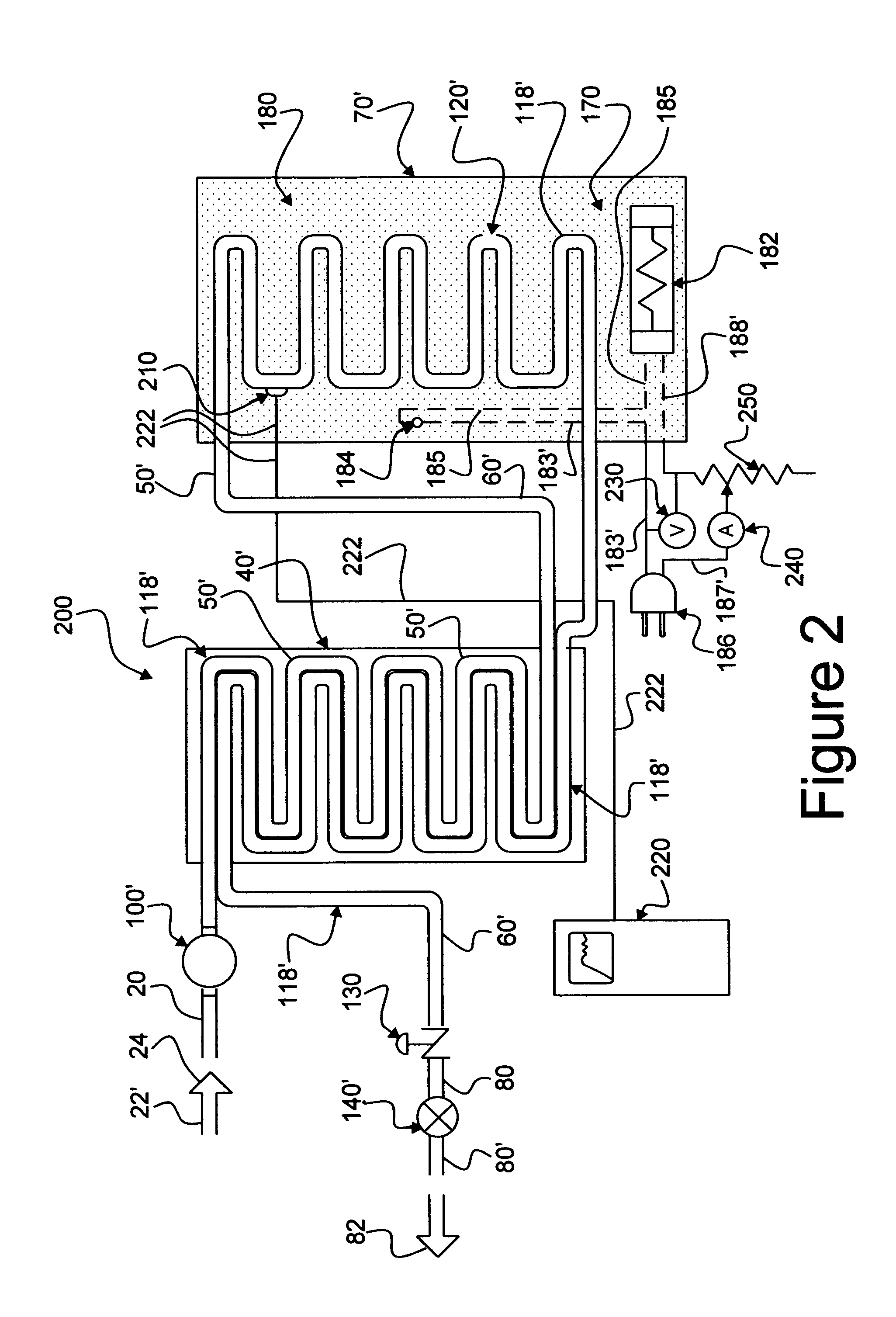
[0033]Reference is now made to the embodiment illustrated in FIG. 1. While only a single embodiment is provided herein, it should be apparent to one skilled in water and other aqueous liquid purification by sterilization that other embodiments may be employed within the scope of the invention.

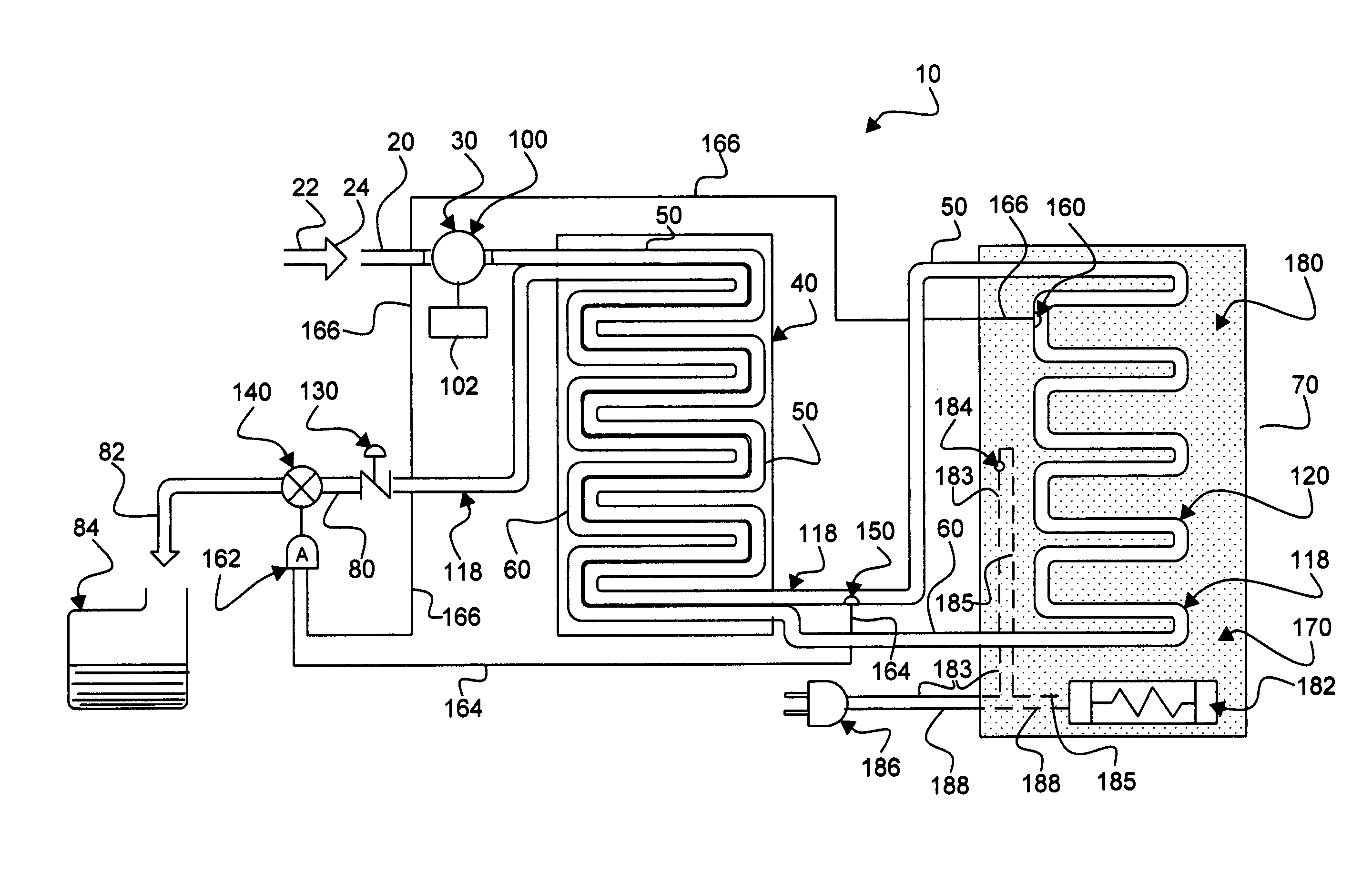
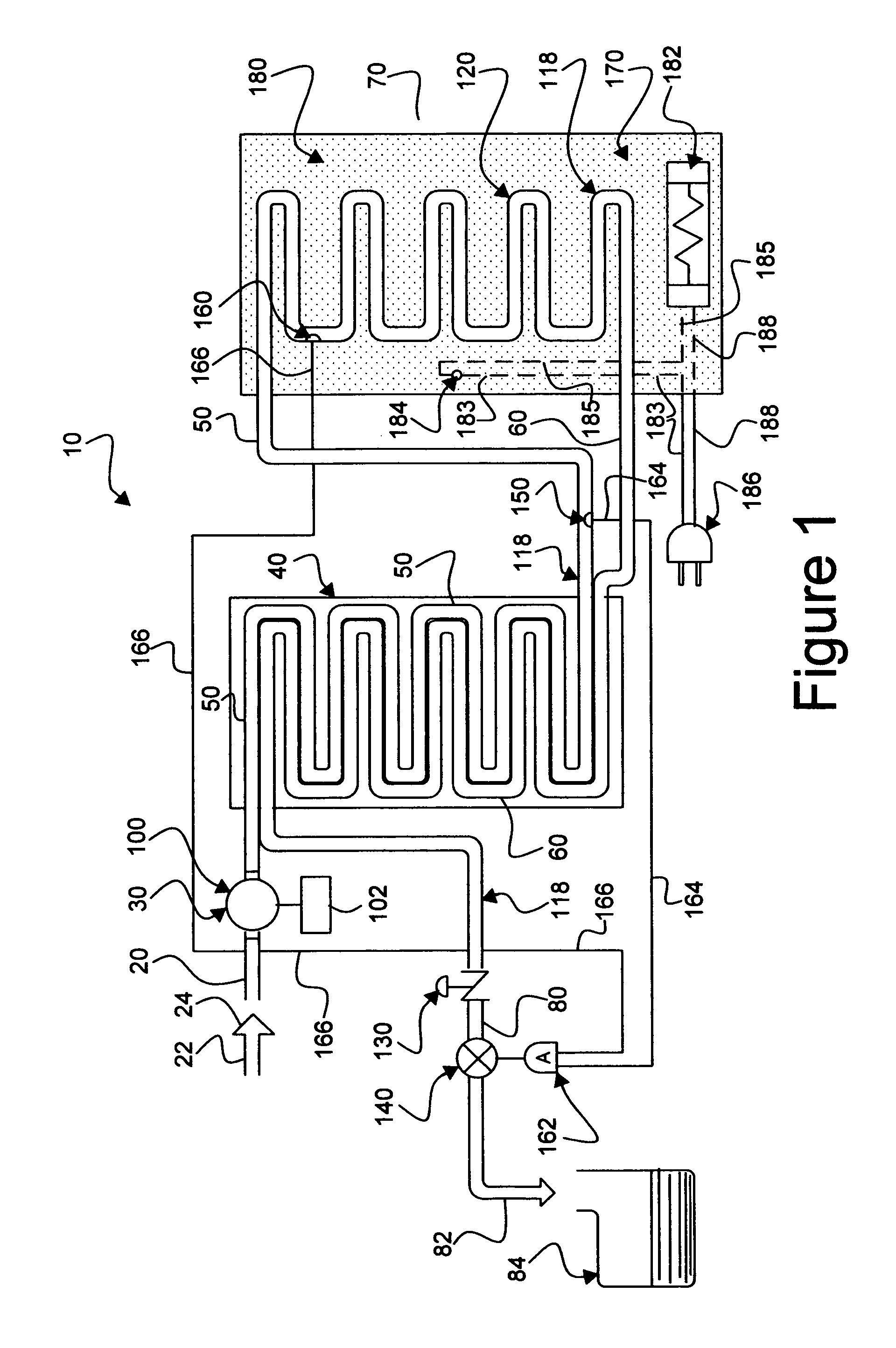
[0034]As seen in FIG. 1, a water sterilization system 10 comprises an influent channel 20, wherethrough water from a source 22 (see arrow 24) is delivered, a flow controller subsystem 30, a heat exchanger 40 through which influent liquid flows in an input pathway 50 and through which effluent liquid flows in an output pathway 6...


PUM

PropertyMeasurementUnit
energyaaaaaaaaaa
pressure dropaaaaaaaaaa
pressureaaaaaaaaaa

Abstract

A flow through aqueous liquid sterilization apparatus which employs substantially fixed temperatures and pressures and variable flow rates through the apparatus for controllably processing aqueous liquids to achieve predetermined values of SALs.

Description

[0001]This U.S. patent application is a Continuation of a U.S. patent application Ser. No. 12 / 008,038, filed Jan. 8, 2008, which is a Continuation-in-Part for U.S. patent application Ser. No. 11 / 210,217, filed Aug. 22, 2005 by John G. Bowen and titled, APPARATUS AND METHODS FOR VARIABLY STERILIZING AQUEOUS LIQUIDS.FIELD OF INVENTION[0002]This invention relates to apparatus and methods by which aqueous (water based) liquids are decontaminated, collected and stored for culinary purposes. This invention is further related to methods which decontaminate such aqueous liquids without use of chemical or light energy processes.BACKGROUND OF THE INVENTION[0003]There is an ever increasing need for new, more effective, efficient and lower cost methods for decontaminating water and other water based (aqueous) liquids. As and example, Center for Disease Control and Prevention (CDC) reports in a Mar. 6, 2003, report on BACTERIAL WATERBORNE DISEASES that each year there are 3.5 billion episodes of...

Claims


Application Information

Patent Timeline
Patent Type & Authority Applications(United States)
IPC IPC(8): C02F1/02
CPCA61L2/04A61L2/28C02F1/006C02F2303/04C02F2209/02C02F2209/03C02F2209/40C02F1/02Y02W10/37
Inventor BOWEN, JOHN GUY
Owner ALDRIDGE PABLO
Why Eureka
Try Eureka