Sealing System For Pressure Vessels

Inactive Publication Date: 2010-09-02
HAYWARD IND INC
View PDF40 Cites 22 Cited by
  • Summary
  • Abstract
  • Description
  • Claims
  • Application Information

AI Technical Summary

Benefits of technology

[0004]The present invention relates to a pressure vessel that includes a housing having separable portions, which are moveable from a first position to a second position. In the first position, the separable portions are substantially retained against each other. In the second position, a passageway is

Problems solved by technology

This could create an unsafe condition if the clamp is not properly assembled or if the pressure vess

Method used


Image

  • Sealing System For Pressure Vessels
  • Sealing System For Pressure Vessels
  • Sealing System For Pressure Vessels

Examples


Example

[0021]The present invention is described in connection with a filter adapted for removing particulate matter from a fluid stream. It should be understood, however, that the present invention can be used with other pressure vessels that employ a gasket, an o-ring, or other sealing materials.

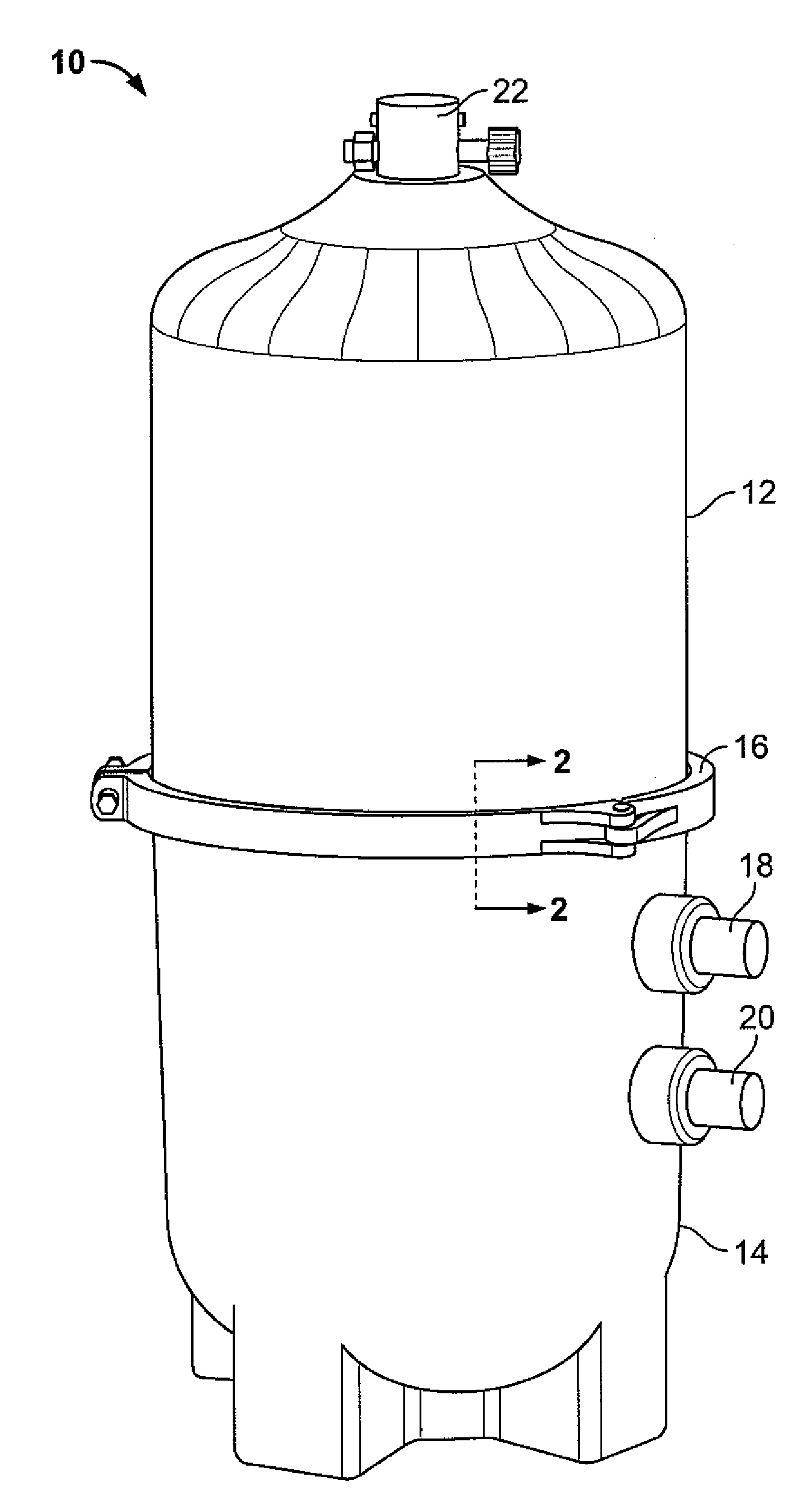
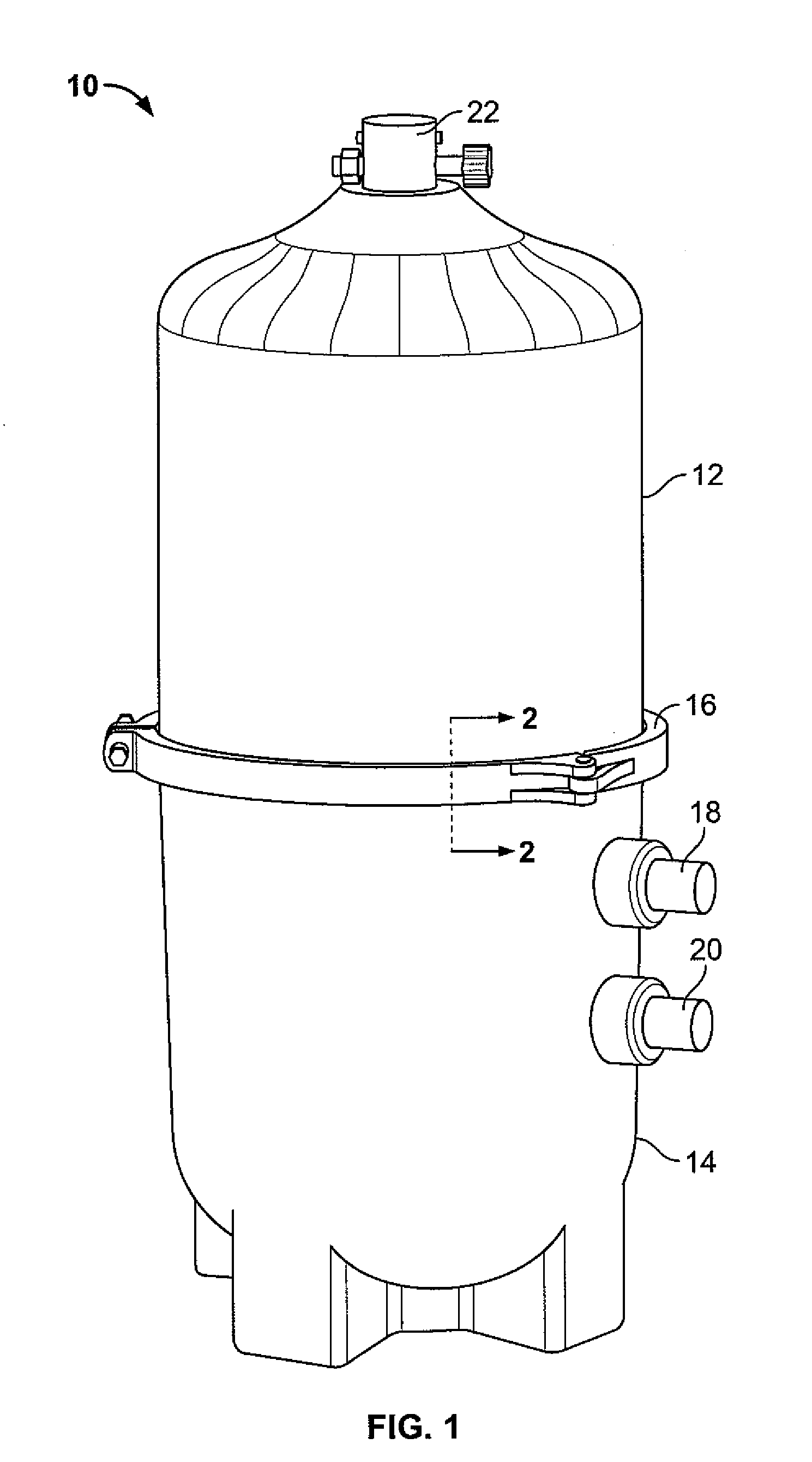
[0022]FIG. 1 illustrates a filter 10 having an upper housing portion 12 and a lower housing portion 14 removably and sealably attached to the upper housing portion 12. The upper and lower housing portions 12, 14 facilitate assembly and maintenance of the filter 10.

[0023]A clamp 16 is used to secure the upper portion 12 of the filter 10 to the lower portion 14 of the filter 10. While the present invention will be described in connection with the clamp 16, it should be understood that the present invention can be used with other types of clamps, or in some other conventional manner for retaining and compressing the upper and lower portions 12, 14 to each other.

[0024]The filter 10 includes an inlet 1...


PUM


Abstract

A pressure vessel that includes a housing having separable portions is provided. A seal is provided in a groove formed between the separable portions. A retaining mechanism is provided for retaining the seal in the groove, wherein the seal is prevented from obstructing a passageway formed between the separable portions when the separable portions have not been properly compressed against each other.

Description

FIELD OF THE INVENTION[0001]The present invention relates to pressure vessels, and more particularly, to a sealing arrangement utilized in a pressure vessel, such as a filter.BACKGROUND OF THE INVENTION[0002]One type of conventional pressure vessels, such as swimming pool filters, include two separable units in order to allow for repeated access to the interior of the pressure vessel for cleaning or replacement, etc. A clamp is utilized to secure the separable units to each other. These pressure vessels are generally equipped with a seal between the separable units in order to prevent leakage when the pressure vessel is properly assembled. The seal is typically designed to maintain its integrity up to the structural limits of the clamp. In this manner, when the clamp is not properly assembled, the seal will maintain its integrity and prevent leakage, while the clamp will be stressed beyond its structural mechanical limits. This could create an unsafe condition if the clamp is not pr...

Claims


Application Information

Patent Timeline
IPC IPC(8): B65D6/02B65D5/36B65D8/10
CPCF16J13/065F16J15/064F16L23/18F16L23/08F16J15/164
Inventor GRIFFIN, RONALD H.LEVIN, ALAN R.ANDERSON, ERICK E.
Owner HAYWARD IND INC
Why Eureka
Try Eureka