

Brachytherapy instrument and methods
- Summary
- Abstract
- Description
- Claims
- Application Information
AI Technical Summary
Benefits of technology
Problems solved by technology
Method used
Image

Examples
first embodiment
Alternative First Embodiment
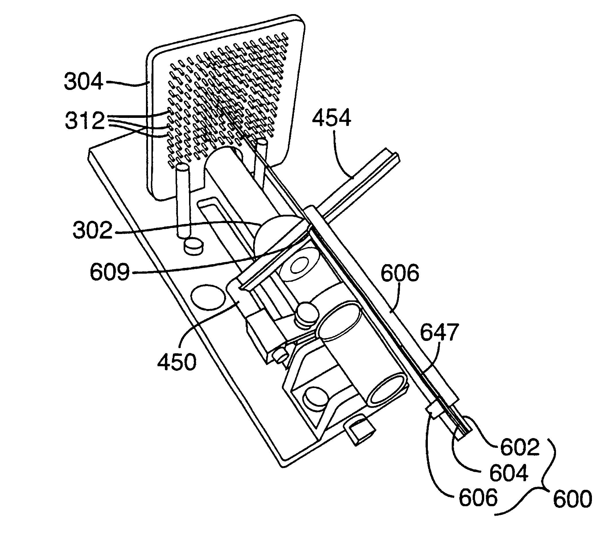
A needle assembly 600 according to an alternative first embodiment is shown in FIGS. 39A-49. In the alternative first embodiment, elements corresponding to the elements of the first embodiment described above are numbered with the first embodiment reference number plus 500.
In the needle assembly 600, the housing 606 and the needle 602 are shaped to cooperate with an optional, separate element, referred to as a pusher 680, that is used to secure the seeds within the assembly before loading (such as during transport), and to load the seeds into the needle 602. Thereafter, the stylet 604 is used as described above to implant the seeds during a procedure.
In the needle assembly 600, correct positioning of the needle tip 608 at the over-insertion and insertion depths is achieved by abutting or engaging different features of the housing 606 with a stationary object (e.g., the template 304 or a stop, such as the stops described below in connection with FIGS. 27-3...
second embodiment
FIGS. 10-16 illustrate a needle assembly 200 according to another embodiment, in which each of the needle and stylet are separately selectively secured or fixed to the housing to allow independent selective movement of the needle and stylet by disengagement from the housing. In this embodiment, elements corresponding to elements of the first embodiment described above are numbered with the first embodiment reference number plus 100. The illustrated construction of the needle assembly 200 minimizes the risk of unintentionally moving the needle 202 and / or the stylet 204 in the axial direction A during a brachytherapy procedure. In general, the needle 202 and the stylet 204 are each independently slidable in the axial direction relative to the housing 206 by direct manipulation of respective knobs projecting outside the housing 206.
As illustrated in FIG. 10, the housing 206 of the needle assembly 200 is generally tubular, with a spread leaf-type spring spacer 209 extending from a forwa...
third embodiment
According to a third embodiment, a stop that prevents the needle from being inserted beyond a desired position is provided. The stop provides a surface which the needle (or needle assembly) contacts to prevent further advancement of the needle / needle assembly in the insertion direction. Optionally, the needle / needle assembly may also be engaged with the stop to stabilize the needle tip and to avoid any inadvertent withdrawal of the needle. According to specific implementations, the stop is removably attached to the ultrasound probe and / or its carriage. Thus, the stop may move with the ultrasound probe / carriage as the probe is initially inserted into the patient.
Referring to FIG. 21, a schematic side view of the conventional brachytherapy system 300, which is generally in accordance with FIG. 17, is shown as modified to include a stop 390. As shown in FIG. 21, the stop 390 is removably attached to the ultrasound probe 310 by a connector 391 at a point spaced from the proximal face 30...
PUM
 Abstract
Description
Claims
Application Information