Modular container holder

Active Publication Date: 2021-09-21
PIERCE CARRICK J
View PDF55 Cites 0 Cited by
  • Summary
  • Abstract
  • Description
  • Claims
  • Application Information

AI Technical Summary

Benefits of technology

[0009]It is another aspect of an example embodiment in the present disclosure to provide a holder capable of being combined with other holders to store a plurality of containers. Accordingly, the present disclosure provides a modular container holder whereby the backing panel has top and lower edges and sides extending therebetween, allowing multiple modular container holders to be contiguously aligned in a column configuration or a row configuration.
[0010]It is yet another aspect of an example embodiment in the present disclosure to provide a holder which allows containers to be inserted or removed without obstruction when the modular container holders are positioned in the column configuration. Accordingly, the present disclosure

Problems solved by technology

However, conventional racks and shelves are fixed in size and shape and cannot be reconfigured or expanded to suit specific storage and organizational needs, causing inefficient use of space.
The spice rack cannot be reconfigured to increase or decrease the number of spaces for containers, in response to changing storage needs.
However, these devices are often tailored towards holding containers with a specific shape and

Method used


Image

  • Modular container holder
  • Modular container holder
  • Modular container holder

Examples


Example

[0032]The present disclosure now will be described more fully hereinafter with reference to the accompanying drawings, which show various example embodiments. However, the present disclosure may be embodied in many different forms and should not be construed as limited to the example embodiments set forth herein. Rather, these example embodiments are provided so that the present disclosure is thorough, complete and fully conveys the scope of the present disclosure to those skilled in the art.

DETAILED DESCRIPTION OF THE PREFERRED EMBODIMENTS

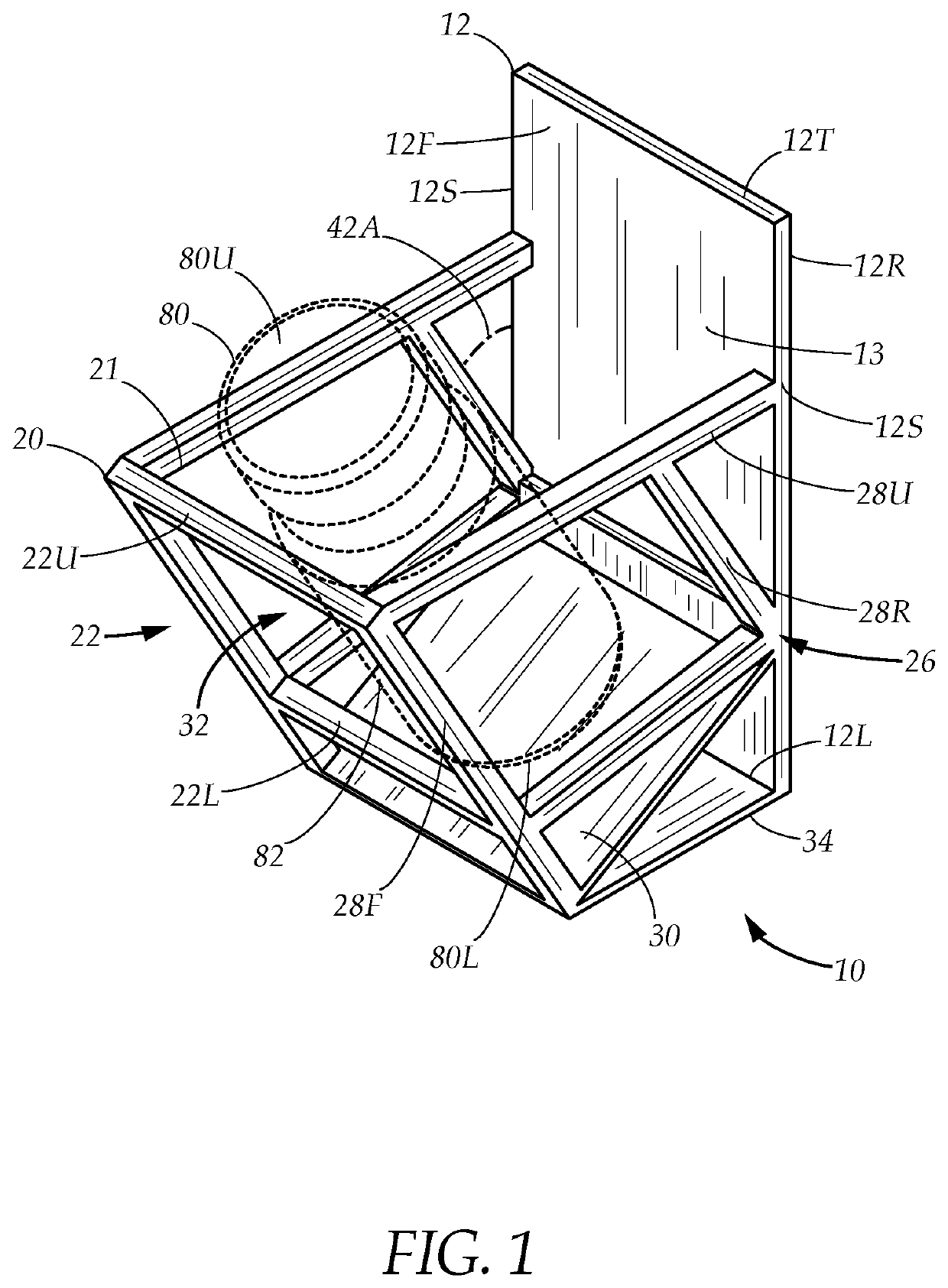
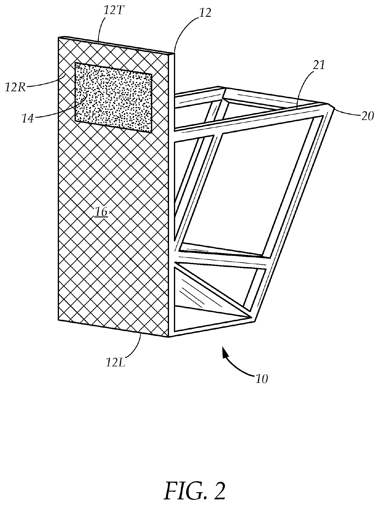
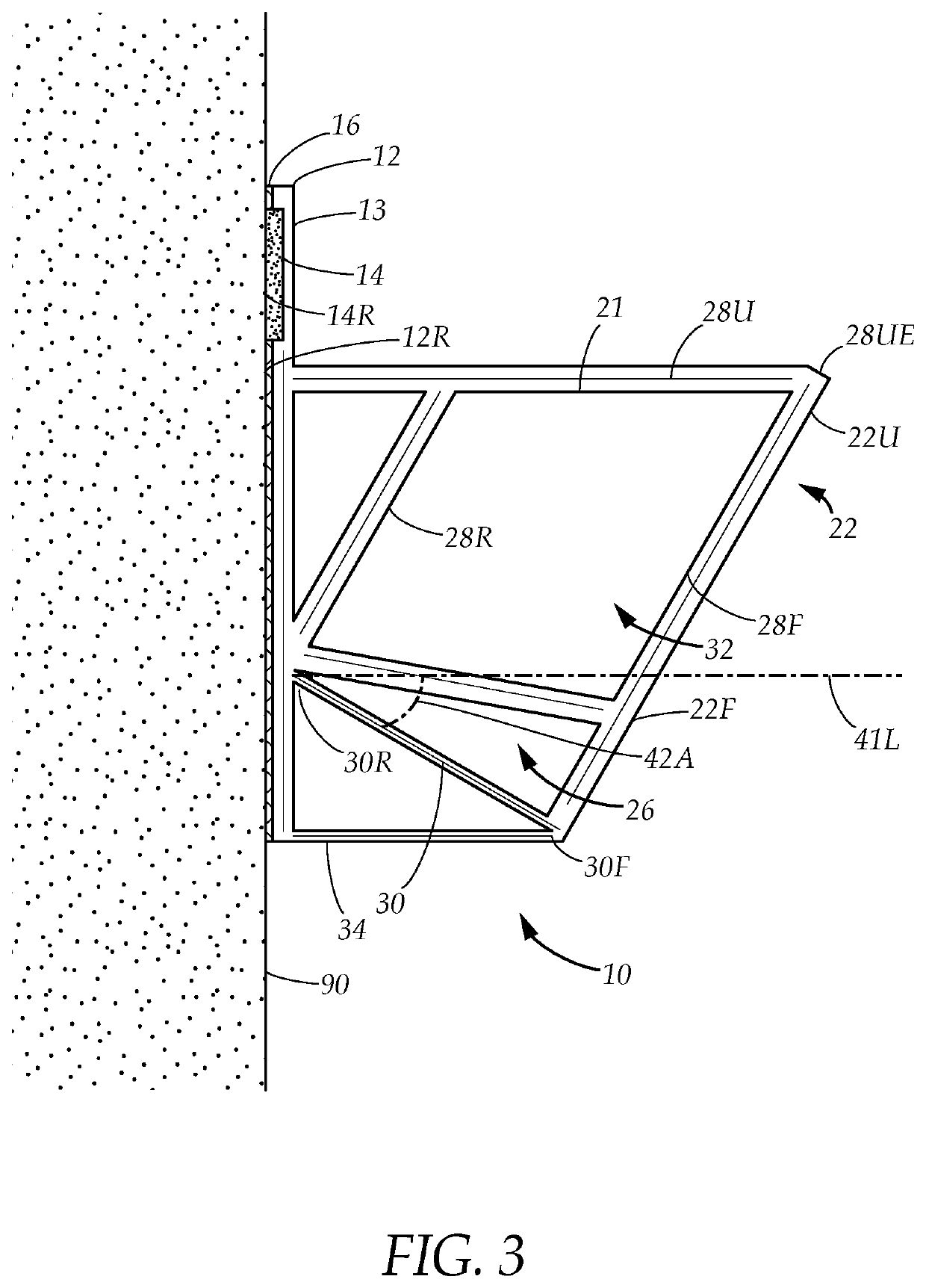
[0033]FIG. 1 illustrates a modular container holder 10 comprising a backing panel 12 and a basket portion 20. The backing panel 12 has a front face 12F, a rear face 12R disposed opposite thereof, a top edge 12T, and a lower edge 12L. The backing panel 12 may further have a pair of sides 12S which extend between the top and lower edges 12T, 12L. The basket portion 20 projects from the front face 12F and tilts forwardly. The basket portion 20 has an...


PUM


Abstract

A modular container holder comprising a backing panel and a basket portion, the backing panel has a selectively attachable mounting panel assembly adapted to detachably secure the modular container holder to a vertical mounting surface, the basket portion projects forwardly from the backing panel and is adapted to receive and retain a container. A contiguous modular arrangement of multiple modular containers positioned in column or row configurations allows multiple containers to be stored, while the basket portion is tilted forwardly to prevent the obstruction of basket openings when the modular container holders are vertically stacked in the column configuration.

Description

[0001]This application is continuation in part of U.S. patent application Ser. No. 16 / 421,830, filed on May 24, 2019, from which priority is claimed and the contents of which are relied upon and incorporated herein by reference in their entirety. This application is also a continuation in part of U.S. patent application Ser. No. 16 / 933,340, filed on Jul. 20, 2020 which is a continuation in part of U.S. patent application Ser. No. 16 / 844,313, filed on Apr. 9, 2020 and was issued as U.S. Pat. No. 10,716,396 on Jul. 21, 2020, which is a division of U.S. patent application Ser. No. 16 / 421,869, filed on May 24, 2019 and issued as U.S. Pat. No. 10,631,634 on Apr. 28, 2020, from which priority is claimed and the contents of which are relied upon and incorporated herein by reference in their entirety. The entire disclosure of any publication or patent document mentioned herein is entirely incorporated by reference.TECHNICAL FIELD[0002]The present disclosure relates generally to a reposition...

Claims


Application Information

Patent Timeline
IPC IPC(8): A47B43/00A47G29/08A47B87/00A47F7/28A47B81/00A47G23/02A47B73/00
CPCA47B43/00A47B73/008A47B81/00A47B87/007A47F7/28A47G23/0216A47G29/08A47J47/16A47B73/006A47B96/021A47G23/0225
Inventor PIERCE, CARRICK J.
Owner PIERCE CARRICK J
Why Eureka
Try Eureka