Muzzle brake and method

Inactive Publication Date: 2010-09-09
LANGNER F RICHARD
View PDF23 Cites 11 Cited by
  • Summary
  • Abstract
  • Description
  • Claims
  • Application Information

AI Technical Summary

Benefits of technology

[0007]In accordance with one embodiment of the present invention, a muzzle gas reduction device is disclosed. The device comprises, in combination: an upper, elongated, curved section having a first width; a lower, elongated, curved section having a second width greater than that of the first width; wherein the upper and lower, elongated, curved sections define a barrel open to sides thereof; a plurality of cone-shaped combs interposed at intervals along the barrel defined by the upper and lower, elongated, curved sections; wherein each of the cone-shaped combs has an opening therethrough sufficient to permit passage of a projectile; and a coupling device adapted to couple the barrel of the muzzle gas reduction device to a barrel of a firearm.
[0008]In accordance with another embodiment of the present invention, a muzzle gas reduction device is disclosed. The device comprises, in combination: an upper, elongated, curved section having a first width; a lower, elongated, curved section having a second width greater than that of the first width; wherein the upper and lower, elongated, curved sections define a barrel open to sides thereof; at least three cone-shaped combs interposed at intervals along the barrel defined by the upper an

Problems solved by technology

If the shot is successful, the power source is destroyed and the IED is disabled.
There are several limitations with the prior art method herein described.
If the PAN disrupter is too close to the IED, the muzzle gases may detonate the explosive.
Because typical PAN disrupter ammunition generates a substantial amount of muzzle gases, firing of the device also produces significant recoil.
This can be damaging to the PAN disrupter or to a robot upon which it is transported.

Method used


Image

  • Muzzle brake and method
  • Muzzle brake and method
  • Muzzle brake and method

Examples


Embodiment Construction

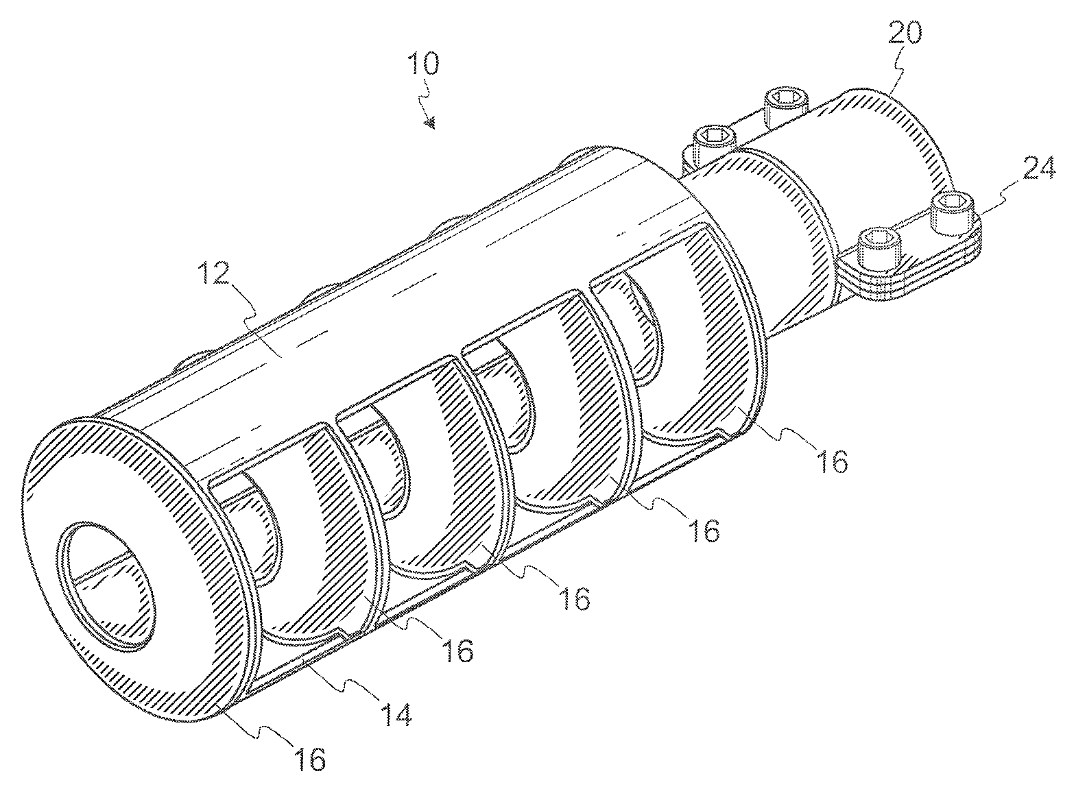
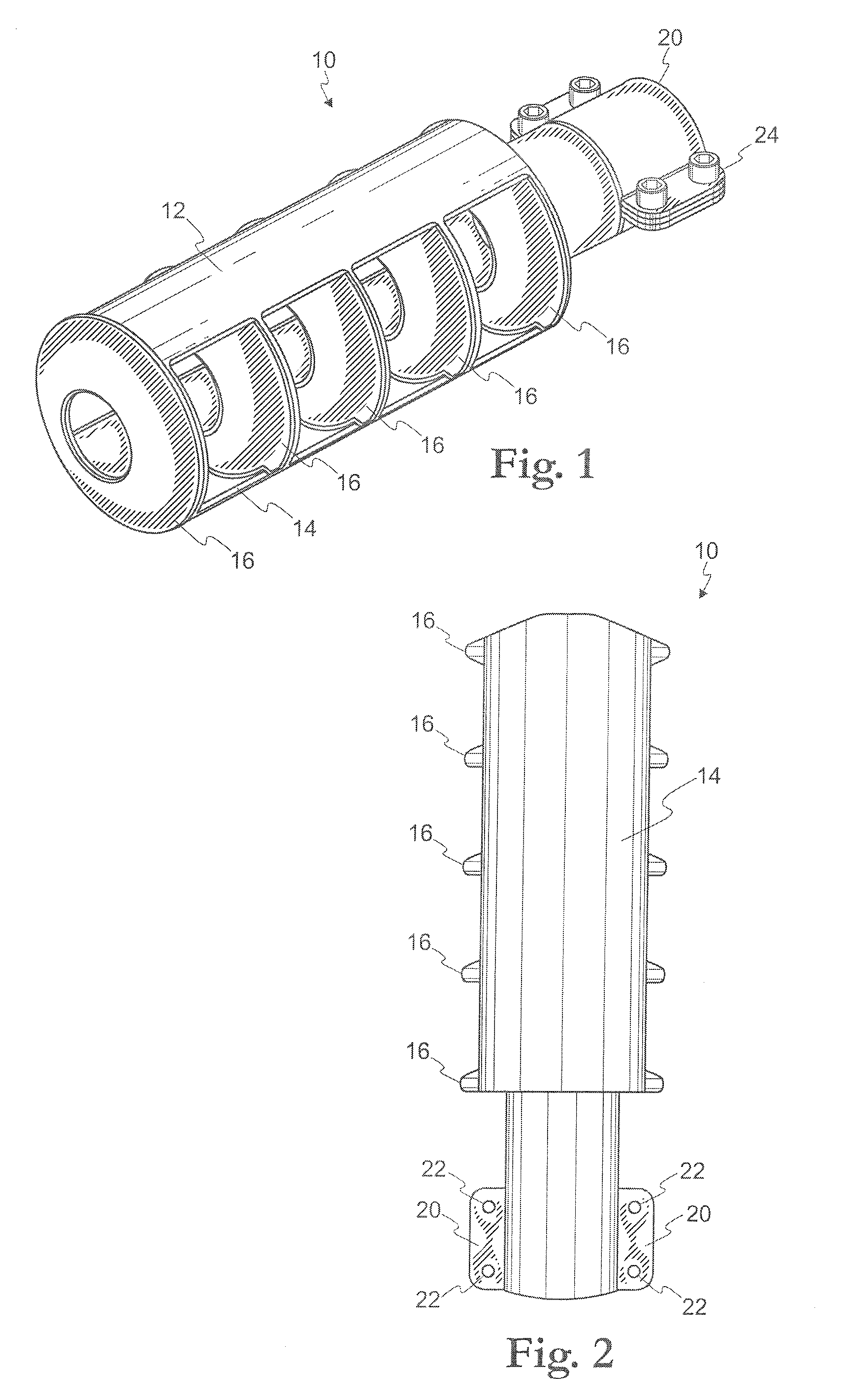
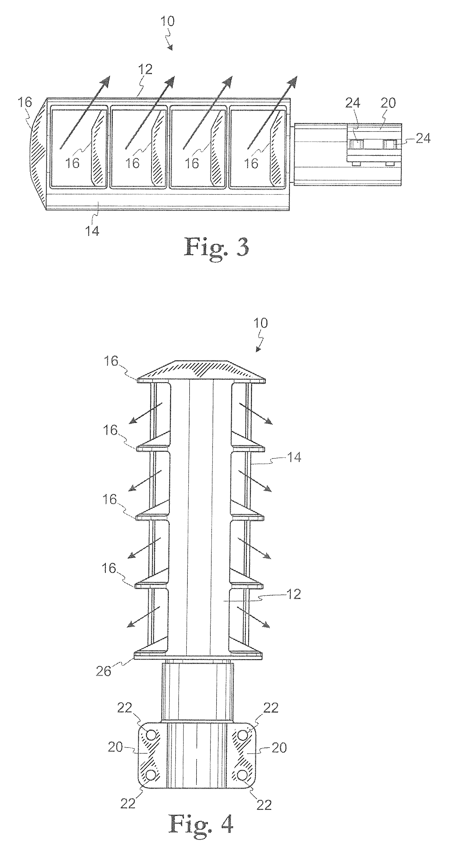
[0015]Referring initially to FIGS. 1-4, an embodiment of a muzzle gas reduction device 10 is shown. The muzzle gas reduction device 10 is adapted, as described below, to be coupled to an end of a firearm barrel. Preferably, the firearm is a PAN disrupter, though the muzzle gas reduction device 10 of the present invention may be utilized with other types of firearms not associated with disruptors, including canons. The muzzle gas reduction device 10 is adapted to permit a projectile to be fired from the firearm, to pass through the device 10, and to divert sideward and upward muzzle gasses escaping from the end of the firearm barrel.

[0016]The device 10 has, as illustrated in the figures, a substantially barrel shape. It comprises an upper, elongated, curved section 12 and a lower, elongated, curved section 14. As best seen in FIGS. 1 and 4, a width of the upper section 12 is less than a width of the lower section 14.

[0017]Interposed between the upper section 12 and lower section 14 a...


PUM


Abstract

A muzzle gas reduction device has upper and lower elongated, curved sections that define a barrel shape that is open to the sides. The upper section has a narrower width than the lower section. A plurality of cone-shaped, open, combs are interposed between the upper and lower elongated sections, along a length thereof. The device is coupled to the end of a barrel of a firearm, preferably a PAN disrupter. The configuration of the cones and the differing widths of the upper and lower sections cause muzzle gasses to be re-directed rearward and upward, reducing recoil.

Description

RELATED APPLICATION[0001]This non-provisional application claims priority from provisional application No. 61 / 209,264, filed on Mar. 6, 2009.FIELD OF THE INVENTION[0002]The present invention relates generally to muzzle brakes and methods therefore and, more particularly, to an improved muzzle brake and method having particular application to the disabling of improved explosive devices.BACKGROUND OF THE INVENTION[0003]Percussion actuated non-electric (PAN) disrupters or dearmers are often used by military personnel, bomb squads, and other emergency service personnel in the destruction and disablement of improvised explosive devices (IEDs) and other bombs and / or ordnance. A typical PAN disrupter comprises a heavy duty 12-gauge shotgun barrel which can be operated remotely through the use of a robot, for example, in order to facilitate firing of the device from a safe distance. The PAN disrupter is often engaged electrically or by a shock tube. Such a PAN disrupter uses specially desig...

Claims


Application Information

Patent Timeline
IPC IPC(8): F41A21/36
CPCF41A21/36F41A21/34
Inventor LANGNER, F. RICHARD
Owner LANGNER F RICHARD
Why Eureka
Try Eureka