
Fuze for Stun Grenade

a technology of fuzes and grenades, which is applied in the direction of time fuzes, hand grenades, ammunition fuzes, etc., can solve problems such as injury to a nearby person

Inactive Publication Date: 2010-09-09
SAFARILAND
View PDF12 Cites 11 Cited by
  • Summary
  • Abstract
  • Description
  • Claims
  • Application Information

AI Technical Summary

Problems solved by technology

The force that is transmitted into the fuze body by the explosion byproducts can undesirably cause the fuze head to separate, or the fuze body otherwise to fragment, consequences that could undesirably result in injury to a nearby person.

Method used


Image

  • Fuze for Stun Grenade
  • Fuze for Stun Grenade
  • Fuze for Stun Grenade

Examples


Embodiment Construction

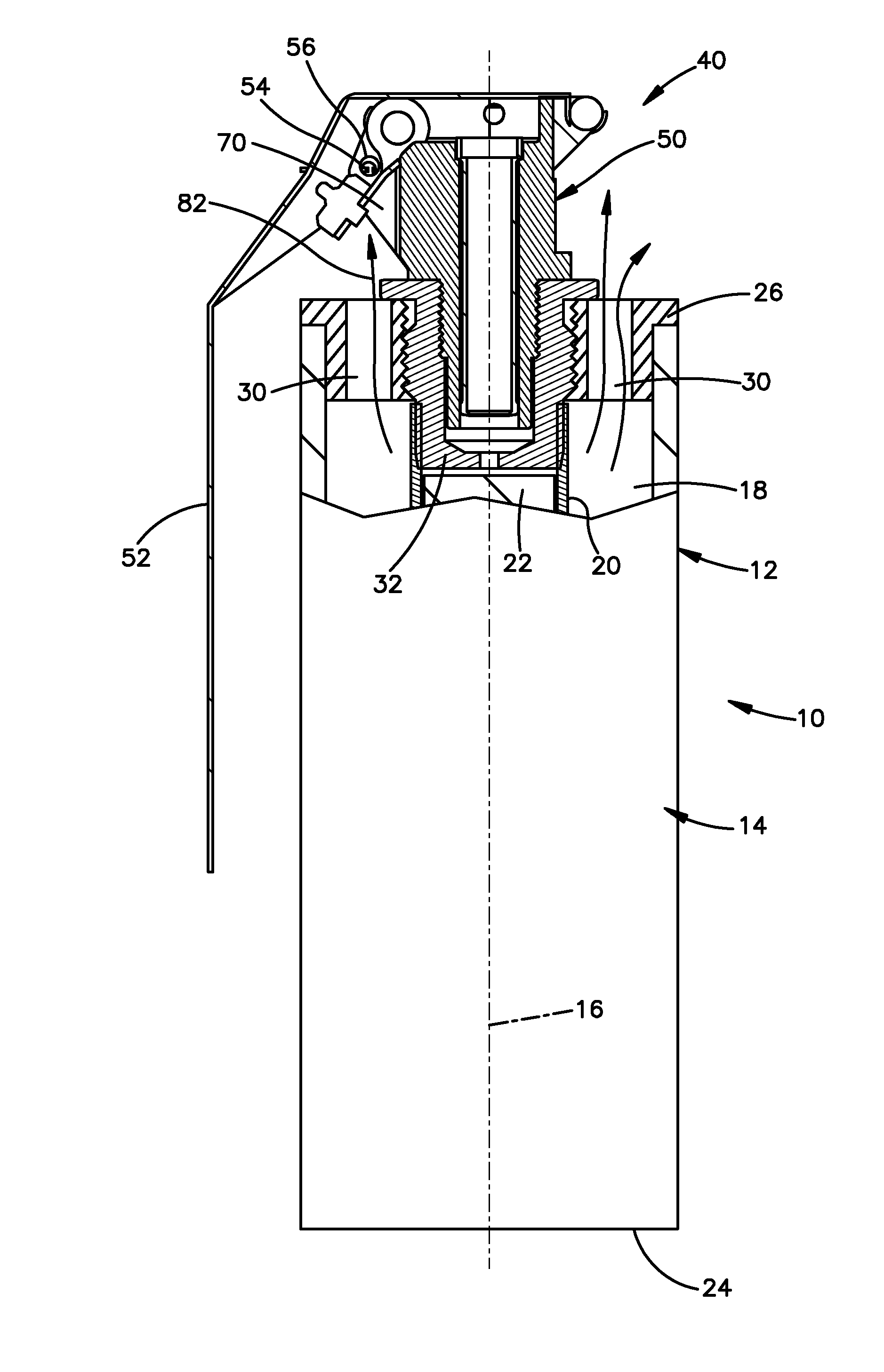
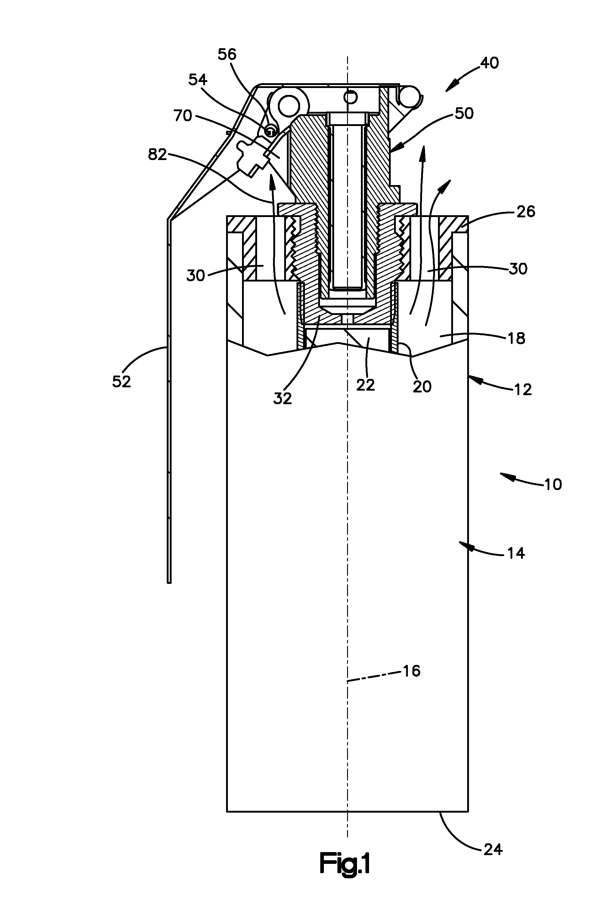
[0012]This invention relates to stun grenades, and in particular relates to a stun grenade with a fuze body that is configured to minimize the possibility of separation or fragmentation. The invention is applicable to stun grenades of varying and different configurations. As representative of the invention, FIG. 1 illustrates a stun grenade 10 constructed in accordance with a first embodiment of the invention.

[0013]The stun grenade 10 includes a housing 12. The housing 12 includes a main body 14 having a cylindrical configuration centered on a longitudinal central axis 16 of the device 10. The main body 14 defines a cylindrical chamber 18 for receiving a cartridge 20 containing a charge 22 such as an explosive mixture that when activated generates explosion byproducts including gas under pressure as well as a bright flash and a loud bang. A bottom wall 24 closes one end of the chamber 18 and a top wall 26 the other end of the chamber.

[0014]The top wall 26 has a plurality of outlet p...


PUM


Abstract

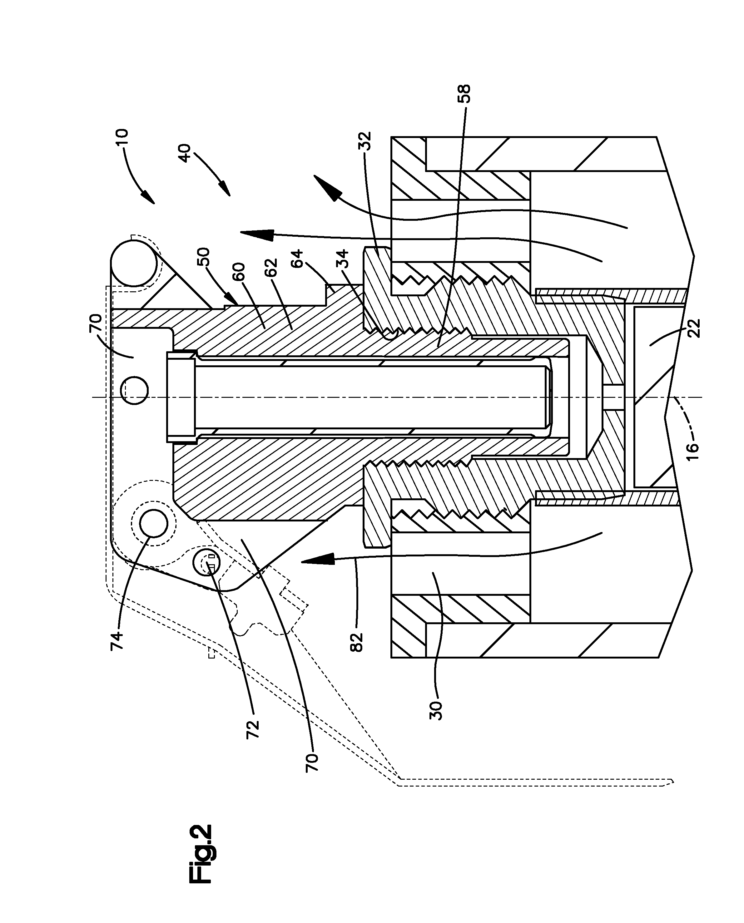
A stun grenade includes a fuze assembly secured to a housing adjacent gas outlet ports. The fuze assembly includes a fuze body having contact surfaces located in the flow path of the gas from the outlet ports so that gas flowing from the outlet ports impinges on the contact surfaces. The contact surfaces of the fuze body extend at an angle of no more than about 50 degrees to the first direction.

Description

RELATED APPLICATIONS[0001]This application claims the benefit of the filing date of U.S. Provisional Application No. 61 / 158,673, filed Mar. 9, 2009, titled Improved Distraction Device Fuze, the entire disclosure of which is incorporated by reference.BACKGROUND OF THE INVENTION[0002]Explosive grenades are designed to cause fragmentation of most or all of their parts, including the housing and the fuze body, so as to inflict maximum damage on a person who is nearby when the device explodes.[0003]More recently, a class of grenades have been designed that are variously known as stun grenades, or flash-bang devices. These devices are not intended to cause physical harm, but rather are intended to temporarily stun a person with a loud sound, a bright flash, and a pressure wave. Such devices are intended to be activated near the person and thus must not fragment or they could cause serious harm to the person.[0004]Many of these less lethal devices use carry-over parts from fragmentation gr...

Claims


Application Information

Patent Timeline
Patent Type & Authority Applications(United States)
IPC IPC(8): F42B8/26F42B12/46F42C19/00
CPCF42B8/26F42B12/42F42B12/46F42C19/02F42C14/02F41H9/00F42B27/00F42C9/10F42B12/36
Inventor KAPELES, JOHN A.HULTMAN, JOHN A.
Owner SAFARILAND
Learn More