
Multiple report stun grenade

a stun grenade and multi-report technology, applied in the field of stun grenades, can solve problems such as serious injury, and achieve the effects of minimizing the risk of serious injury, convenient gripping, and advantageous configuration

Active Publication Date: 2011-06-21
COMBINED SYST
View PDF10 Cites 27 Cited by
  • Summary
  • Abstract
  • Description
  • Claims
  • Application Information

AI Technical Summary

Benefits of technology

[0004]One such device is shown in U.S. Pat. No. 5,654,523 to Brunn, titled “Stun Grenade.” This “single-bang” device has an advantageous configuration. Like many others, it is a cylindrical body sized to readily be gripped by an adult hand, so that the device is secure in the user's fist, with the ends of the cylinder protruding beyond each end of the user's fist. The disclosed device has the advantage that all the vent holes for releasing the energy of the flash charge material come out the ends of the grenade body. While a device normally discharges only after a delay following release by the user, there is a remote possibility that the grenade may discharge while still in the user's hand, such as if the user is distracted, or the device snags on the user's glove. The disclosed device minimizes the risk of serious injury in such an event by discharging the combustion gases out the ends of the device, with no apertures in the cylindrical sidewall of the device.
[0007]Accordingly, there is a need for a multiple-report stun grenade device that provides safe function even in the event of unexpected discharge while in a user's hand.

Problems solved by technology

While a device normally discharges only after a delay following release by the user, there is a remote possibility that the grenade may discharge while still in the user's hand, such as if the user is distracted, or the device snags on the user's glove.
The Nico device suffers the disadvantage of having the flash charge materials projecting their discharge energy exactly where a user's hand grips the device, risking serious injury in the event of a discharge while the device is still being held.

Method used


Image

  • Multiple report stun grenade
  • Multiple report stun grenade
  • Multiple report stun grenade

Examples


Embodiment Construction

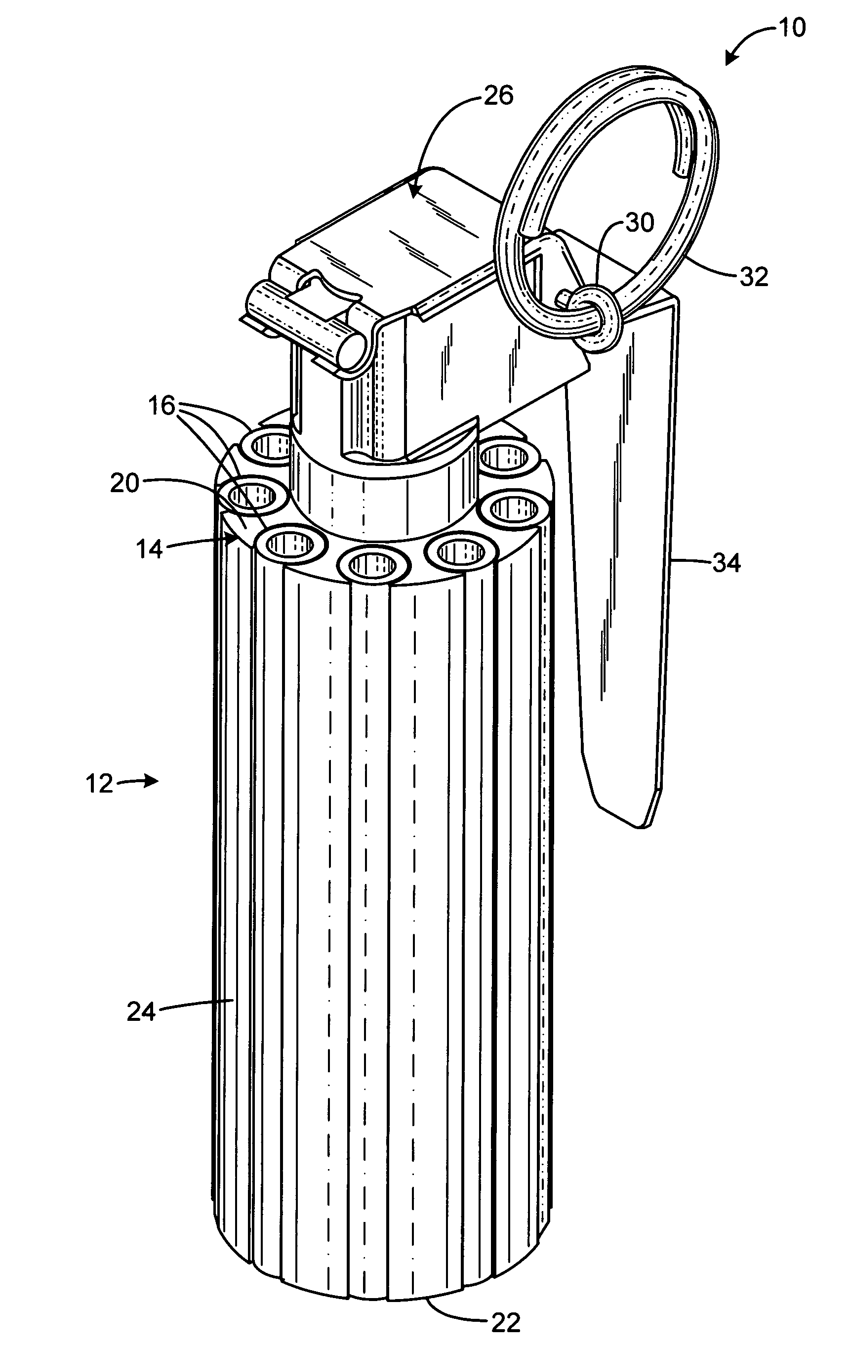
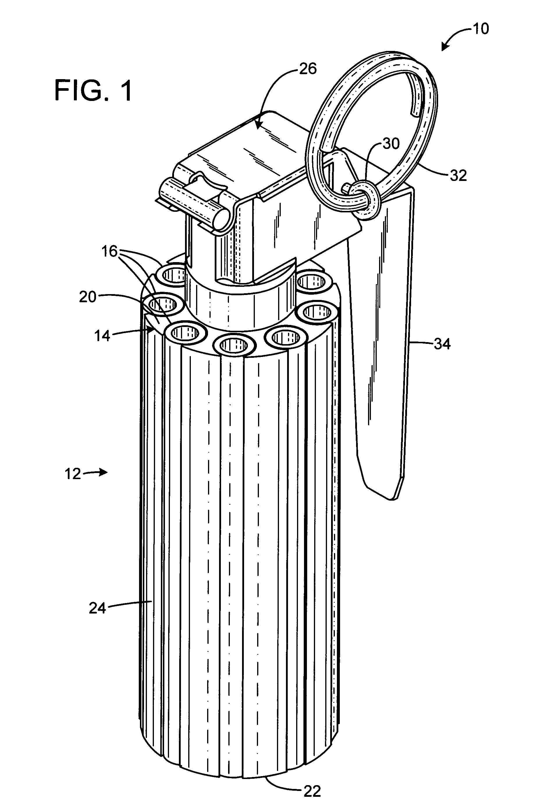
[0017]FIG. 1 shows a flash-bang pyrotechnic device 10 having a cylindrical body 12 formed of a cylindrical frame 14 holding nine sleeves 16. The body has a top end face 20, a bottom end face 22, and a cylindrical sidewall 24. A fuse assembly 26 protrudes from the top end face and includes a safety pin 30 with connected extraction ring 32 and a spring-loaded paddle 34 that initiates a discharge sequence when the paddle is released after the safety pin is removed.

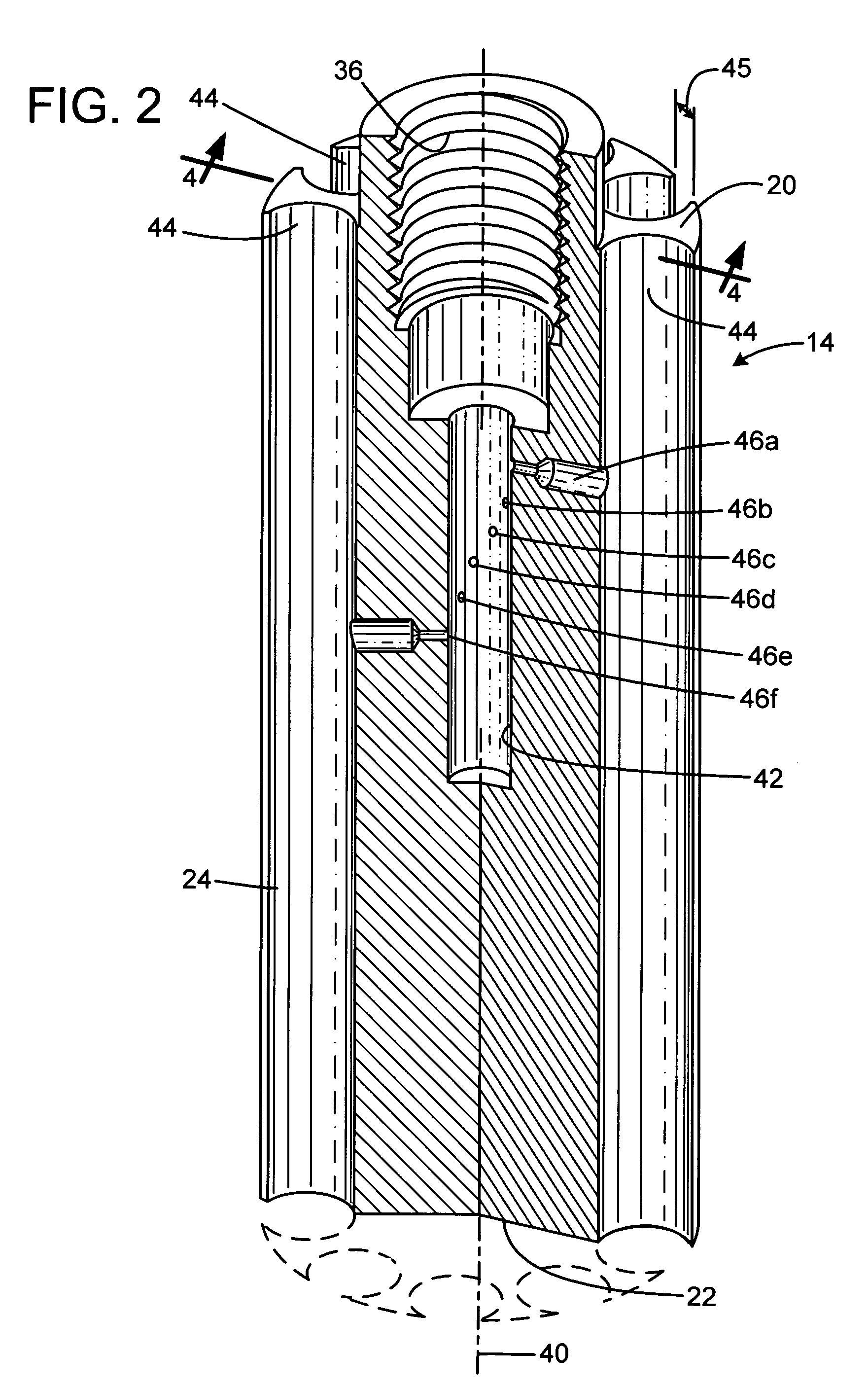
[0018]FIG. 2 shows the frame 14 in a cut-away view. The frame is a straight cylindrical body formed of a monolithic unitary block of material. In the preferred embodiment, it is formed as an aluminum extrusion, with the source extrusion including all the features that run the entire length of the frame, and with the other features being formed by post-machining. In the description, its form may be described in terms of machining steps to produce it from bar stock as opposed to extrusion, in order to explain the structure more...


PUM


Abstract

The present invention overcomes the limitations of the prior art by providing a stun grenade device with an elongated cylindrical body having a cylindrical sidewall and opposed top and bottom end faces. The body includes a delay chamber containing a delay material, and has a number of flash charge chambers each containing a quantity of flash charge material. The body defines a number of ignition passages, each communicating from a respective flash charge chamber to the delay chamber. Each flash charge chamber has at least one exhaust aperture penetrating the top or bottom end face. Each flash charge chamber may be formed in an elongated tubular sleeve inset in a frame of a different material.

Description

FIELD OF THE INVENTION[0001]This invention relates to stun grenades employed by law enforcement and military as distraction devices.BACKGROUND AND SUMMARY OF THE INVENTION[0002]Stun grenades, or “flash-bang” devices are used by military and law enforcement as non-lethal devices intended to distract or stun dangerous suspects or adversaries. Such devices are deployed to minimize hostile responses, and to generate compliance.[0003]A typical existing device employs a “single bang” provided by a quantity of flash-charge material (such as a mixture of aluminum powder and potassium perchlorate) that is detonated after a brief delay. A fuse is activated by release of a handle as in a typical grenade, and the fuse ignites a column of delay material (such as black powder or Zirconium Nickel). The column provides a delay (typically ½ second) until the flame front in the delay material reaches an aperture that communicates with the flash-charge material, igniting it to provide a bright flash a...

Claims


Application Information

Patent Timeline
Patent Type & Authority Patents(United States)
IPC IPC(8): F42B8/00
CPCF42B8/26F42B27/00F42B12/46F42B12/42
Inventor BRUNN, MICHAEL
Owner COMBINED SYST
Learn More