Method and apparatus for dedusting a suction system for a rotary press

Inactive Publication Date: 2010-09-16
FETTE
View PDF17 Cites 4 Cited by
  • Summary
  • Abstract
  • Description
  • Claims
  • Application Information

AI Technical Summary

Benefits of technology

[0007]In the method of the present invention, at least a part of the suction system is flooded with cleaning liquid. The cleaning liquid is subsequently drained into the press room and removed from the same. In the apparatus of the present invention, cut-off valves are disposed in the suction lines for this purpose, which can be selectively closed with the aid of a suitable control device. When these cut-off valves are closed, the cleaning medium which is supplied via a port is dammed up in the suction system. When a predetermined level is reached in one embodiment of the present inven

Problems solved by technology

However, such a cleaning apparatus has some disadvantages.
Due to their way of function, the cleaning nozzles do not have a uniform cleaning effect, and in most cases there are spraying shadows in which no dedusting takes place.
The action range of cleaning nozzles is limited.
This results either in a very high number of cleaning nozzles, or in a worse cleaning result.
The expense for the supply of the cleaning nozzles with cleaning medium is naturally increasing with the number of the cleaning nozzles.
A further disadvantage of the known clean

Method used


Image

  • Method and apparatus for dedusting a suction system for a rotary press
  • Method and apparatus for dedusting a suction system for a rotary press

Examples


Example

[0014]While this invention may be embodied in many different forms, there are described in detail herein a specific preferred embodiment of the invention. This description is an exemplification of the principles of the invention and is not intended to limit the invention to the particular embodiment illustrated

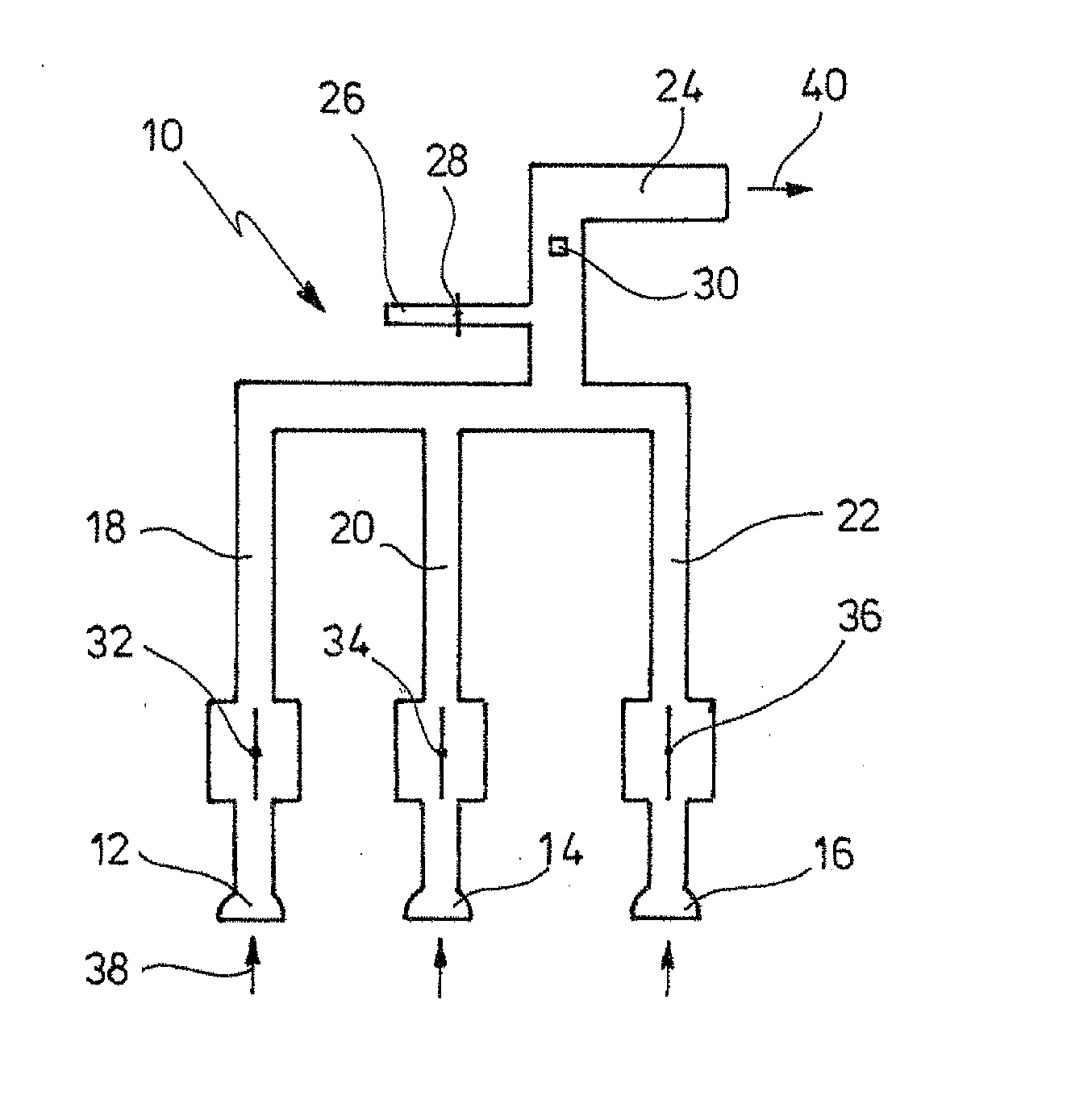
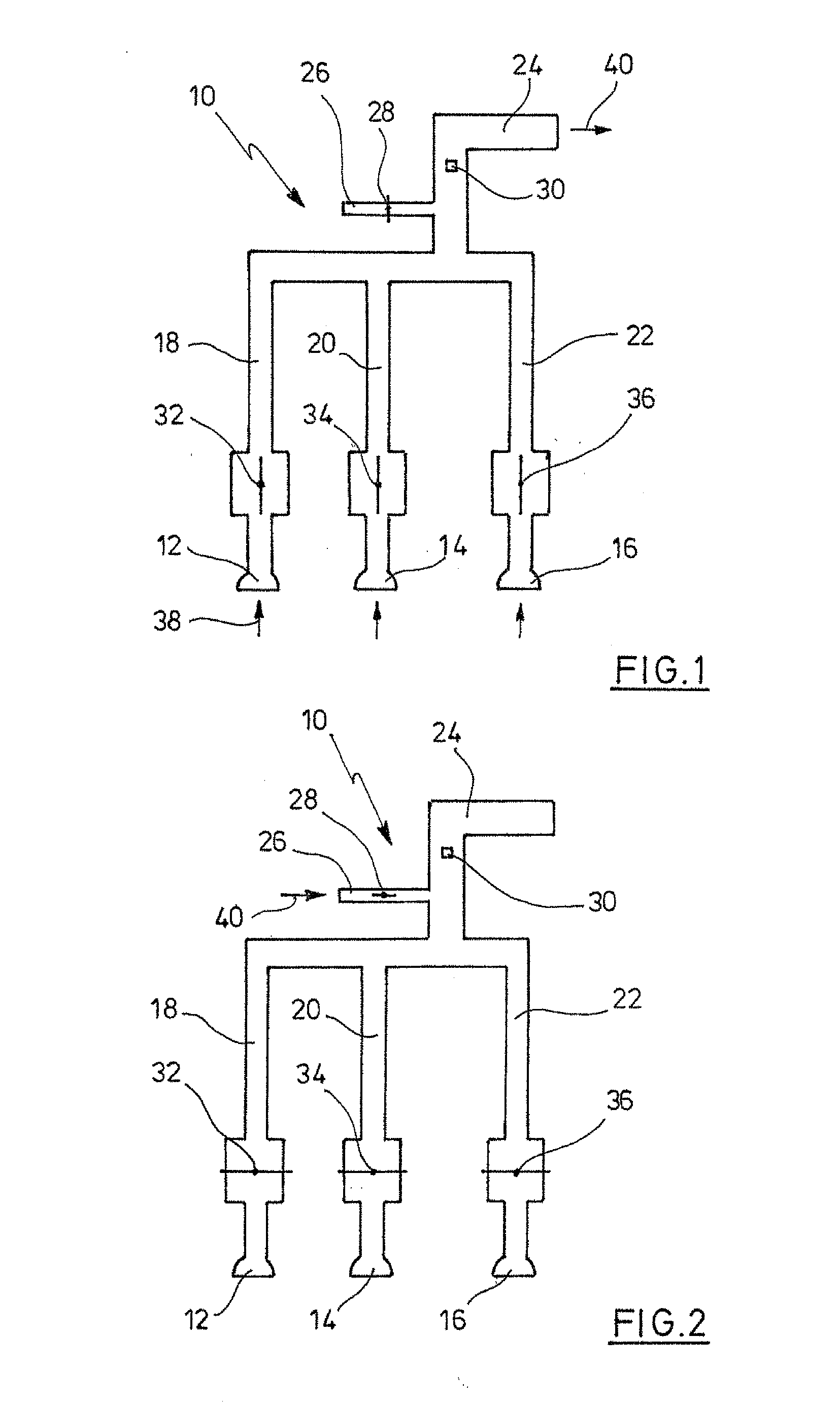
[0015]In FIGS. 1 and 2, a suction system designated with 10 is shown, with whose aid dust and contaminations can be removed from a not shown press chamber of a rotary press. Neither a rotary press nor an aggregate for the suction is shown in the figures. One recognises only three suction nozzles 12, 14, 16, which are disposed at suitable locations in the press room. The suction nozzles 12 to 16 are connected to suction lines 18, 20, 22, which on their part are guided to a collecting line 24. A supply line 26 for cleaning liquid is connected to the collecting line, in which a closing valve 28 is arranged. At the downstream side of the supply line 26, a filling level sensor 30 i...


PUM


Abstract

A method for dedusting a suction system for rotary presses, wherein the cleaning liquid is guided into the suction system, and wherein the suction system is closed in the region of the press room of the press, and at least a part of the suction system is flooded with cleaning liquid, and the cleaning liquid is subsequently drained into the press room.

Description

CROSS-REFERENCE TO RELATED APPLICATIONS[0001]Not applicable.STATEMENT REGARDING FEDERALLY SPONSORED RESEARCH[0002]Not applicable.BACKGROUND OF THE INVENTION[0003]With tablet presses, it is known to remove the dust that is generated in the press room via a suitable suction system. Such a suction system contains in most cases several suction nozzles, which are placed at suitable locations in the press room. The suction lines are connected to a suction apparatus outside the press room via a collecting line. It is necessary to clean the suction system from time to time with a cleaning medium, for instance with water.[0004]It is known to associate cleaning nozzles to the suction system or its channel- or line system, respectively, which are provided with cleaning medium via a line. The greater the number of cleaning nozzles, the better the cleaning result. However, such a cleaning apparatus has some disadvantages. Due to their way of function, the cleaning nozzles do not have a uniform c...

Claims


Application Information

Patent Timeline
IPC IPC(8): B41L41/00
CPCB08B9/00B08B9/027B30B15/0082B30B11/08B08B15/002
Inventor LUEDEMANN, STEFANWOLF, HANS
Owner FETTE
Why Eureka
Try Eureka