
Multiband composite right and left handed (CRLH) slot antenna

a composite right and left-handed (crlh) technology, applied in the direction of slot antennas, antenna details, antennas, etc., can solve the problems that the design of slot antennas may still have limitations on the size reduction, and the size reduction is a challenge at certain frequencies

Active Publication Date: 2010-09-16
TYCO ELECTRONICS SERVICES GMBH
View PDF18 Cites 200 Cited by
  • Summary
  • Abstract
  • Description
  • Claims
  • Application Information

AI Technical Summary

Problems solved by technology

However, slot antenna designs may still have limitations on the size reduction since the antenna size is primarily dependent on a center frequency, thus making the size reduction a challenge at certain frequencies.

Method used


Image

  • Multiband composite right and left handed (CRLH) slot antenna
  • Multiband composite right and left handed (CRLH) slot antenna
  • Multiband composite right and left handed (CRLH) slot antenna

Examples


Embodiment Construction

[0038]As technological advances in the field of wireless communications continue to push mobile devices to increasingly smaller dimensions, compact antenna designs have become one of the most difficult challenges to meet. For example, due to the limited space available in a compact wireless device, a smaller conventional antenna may lead to reduced performance and complex mechanical design assemblies which, in turn, may result in higher manufacturing costs. One possible design solution includes a conventional slot antenna design, which may include a conductive surface having at least one aperture formed in the conductive surface. Because slot antennas are typically formed using a single piece of metal, these types are generally less expensive and easier to build. The slot antenna design may provide several other advantages over conventional antenna designs such as reduced size, simplicity, durability, and integration into compact devices. Reducing the size of the slot antenna, howev...


PUM


Abstract

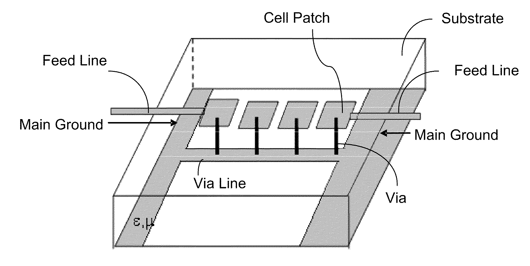
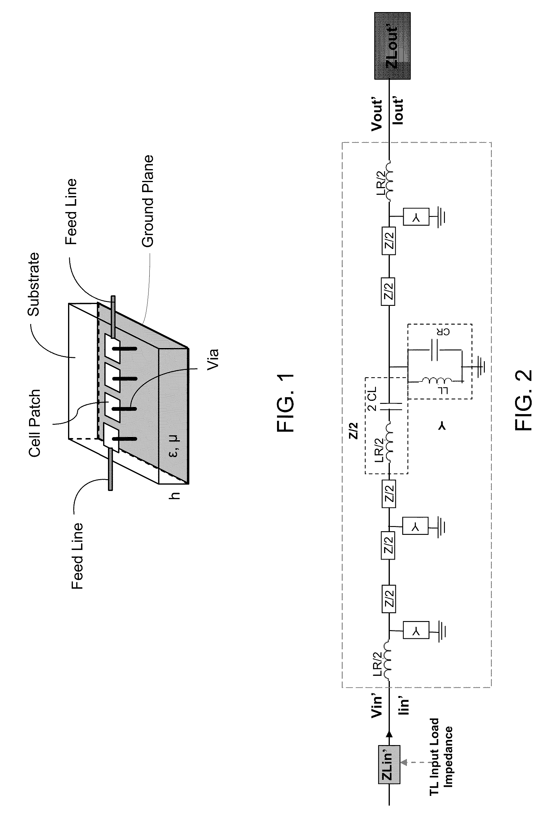
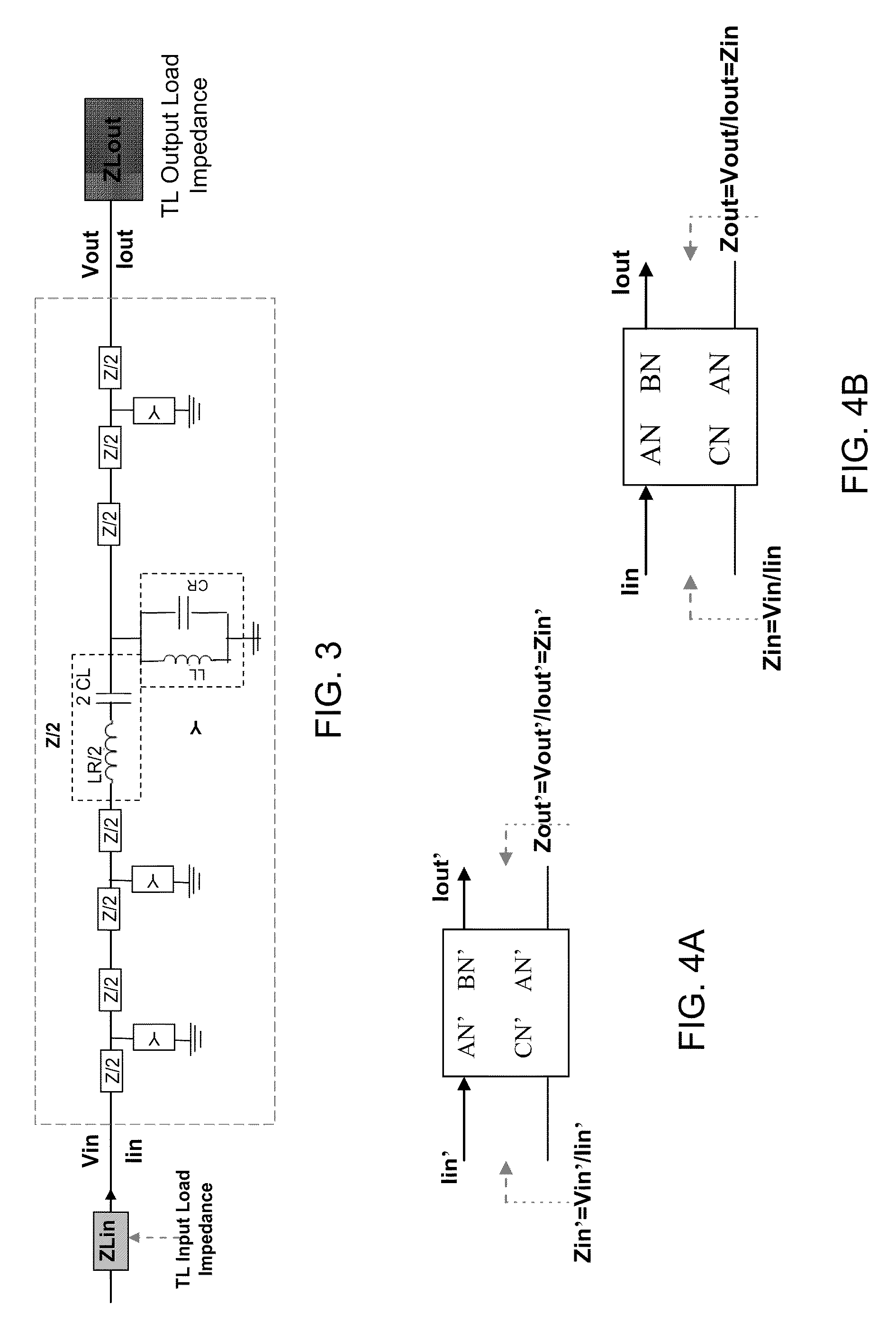
This application relates to slot antenna devices based on Composite Right and Left Handed (CRLH) metamaterial (MTM) structures.

Description

PRIORITY CLAIMS AND RELATED APPLICATIONS[0001]This application claims the benefits of U.S. Provisional Patent Application Ser. No. 61 / 159,694 entitled “MULTIBAND METAMATERIAL SLOT ANTENNA” and filed on Mar. 12, 2009.[0002]The disclosure of the above application is hereby incorporated by reference as part of the specification of this application.BACKGROUND[0003]A conventional slot antenna is generally made up of a one piece planar metal surface, such as a metal plate, with a hole or slot formed in the metal surface. By design, a slot antenna may be considered structurally complementary to a dipole antenna. For example, a printed dipole antenna on dielectric substrate, having similar shape and size to a printed slot antenna, may be formed by interchanging the conductive material layer on the dielectric substrate and open slot area of the slot antenna and vice versa. Both antennas may be similar in form and have similar electromagnetic wave patterns. Factors determining the radiation p...

Claims


Application Information

Patent Timeline
IPC IPC(8): H01Q13/10H01Q1/00B44C1/22H01Q5/10
CPCH01Q15/0086H01Q13/10
Inventor LEE, CHENG-JUNGGUMMALLA, AJAYACHOUR, MAHA
Owner TYCO ELECTRONICS SERVICES GMBH
Learn More