Fixing device, image forming apparatus incorporating same, and control method for fixing device
- Summary
- Abstract
- Description
- Claims
- Application Information
AI Technical Summary
Benefits of technology
Problems solved by technology
Method used
Image

Examples
first embodiment
[0071]Next, behavior and effect of the fixing device 8 according to a first embodiment is described below.
[0072]FIG. 3 is a graph illustrating changes in the temperature of the fixing belt 31 when the reload control is executed. In FIG. 3, a solid line indicates temperature changes in the reload control according to the present embodiment, and a broken line indicates temperature changes in reload control according to a comparative example.
[0073]In the reload control according to the comparative example depicted in FIG. 3, the fixing process is started after the fixing belt 31 is heated to a predetermined temperature Tup that is higher than a predetermined fixing temperature Tf, in consideration of the decrease in the temperature in continuous fixing.
[0074]By contrast, in the reload control according to the present embodiment, the heating controller 310 controls the induction heating unit 33 such that the heating the fixing belt 31 is heated to the fixing temperature Tf, and followin...
second embodiment
[0092]Next, a fixing device 8A according to a second embodiment is described below.
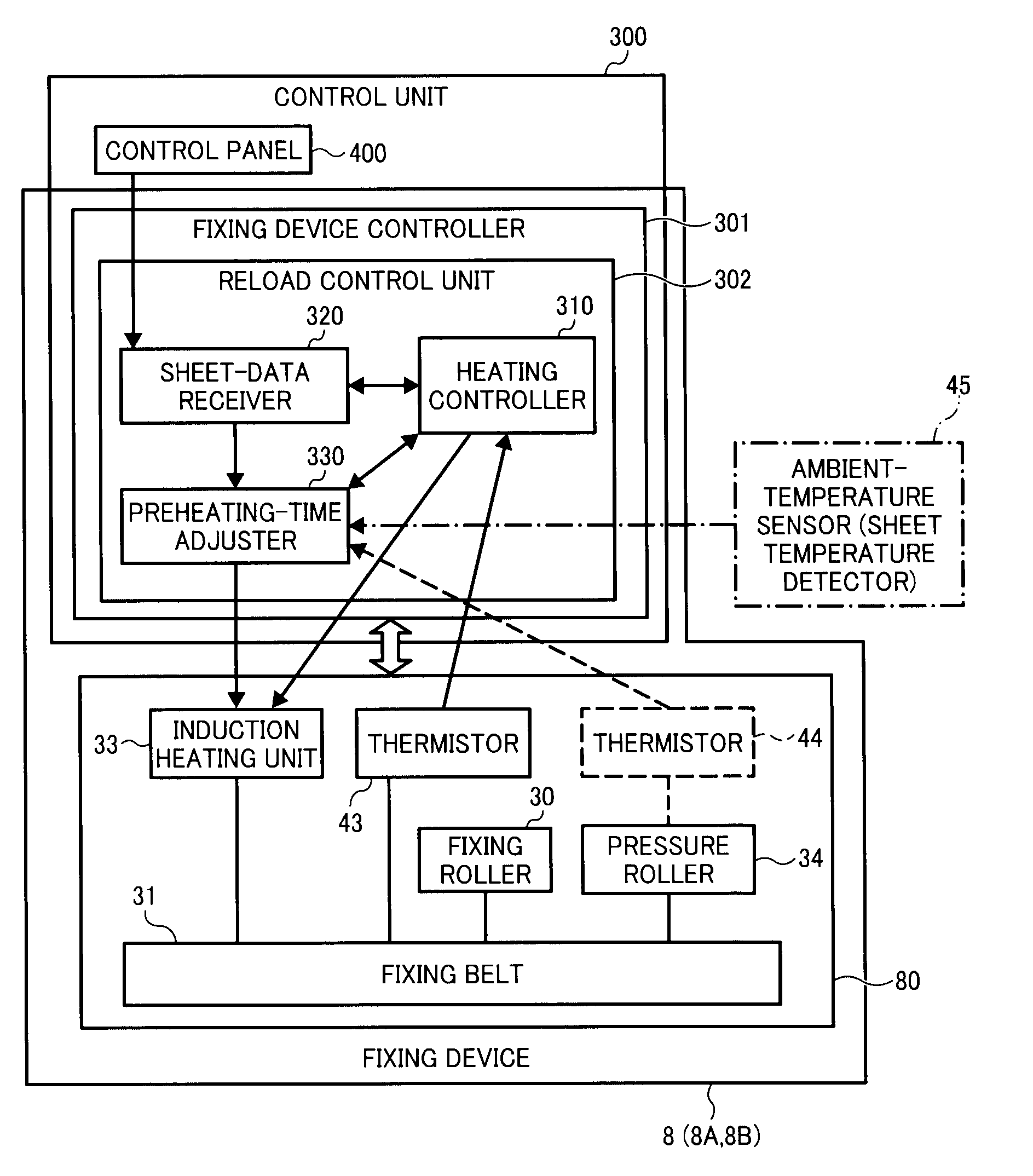
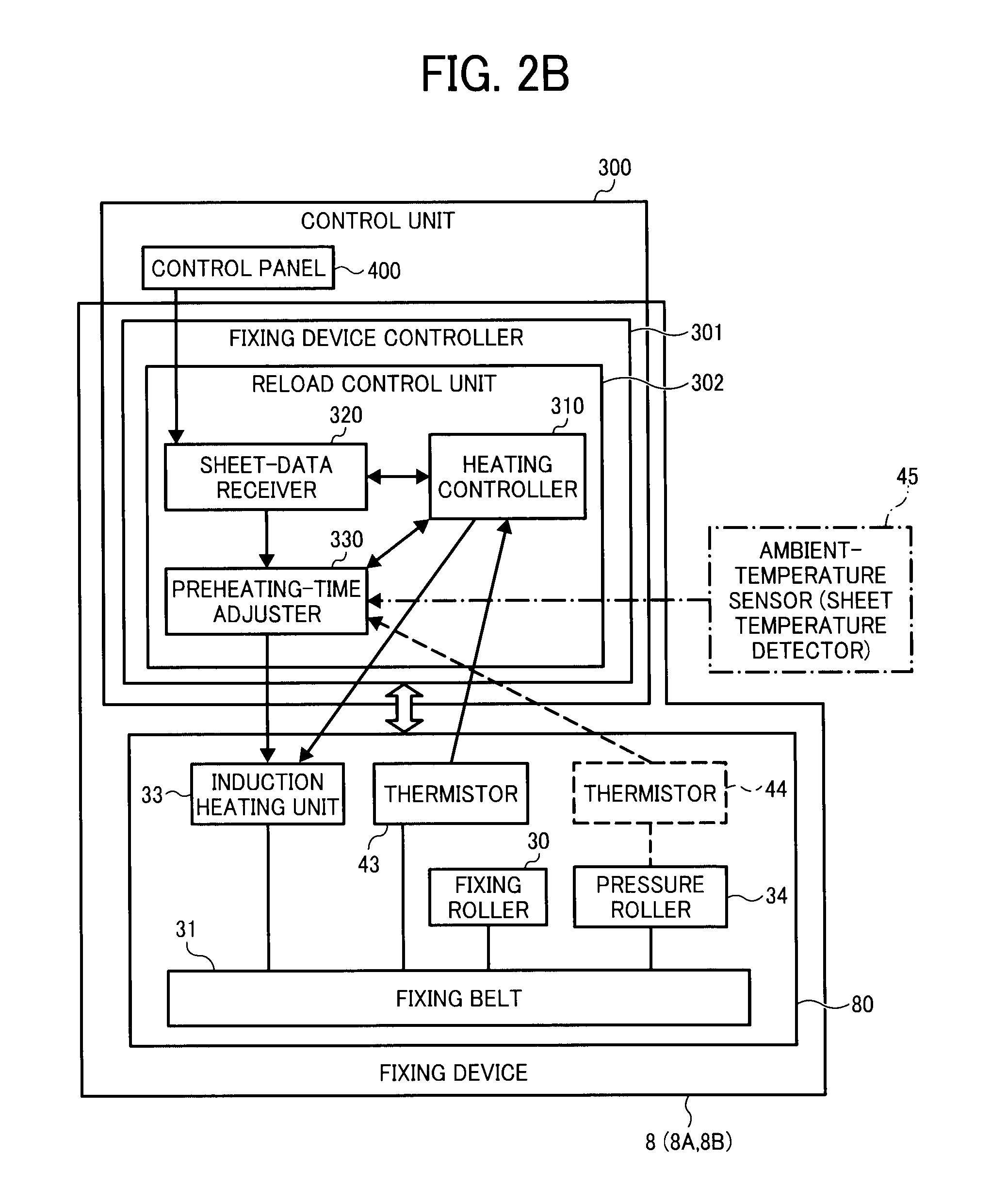
[0093]The fixing device 8A has the same basic operation and configuration as the fixing device 8 of the first embodiment described above, but with the addition of a pressing member temperature detector. That is, the basic operation of the fixing device 8A is similar to the operational process in the flowchart shown in FIG. 4 and moreover has the same components as the components of the fixing device 8 (other than the pressing member temperature detector difference described above) which are represented by identical reference numerals, and therefore a description thereof is omitted for simplicity.
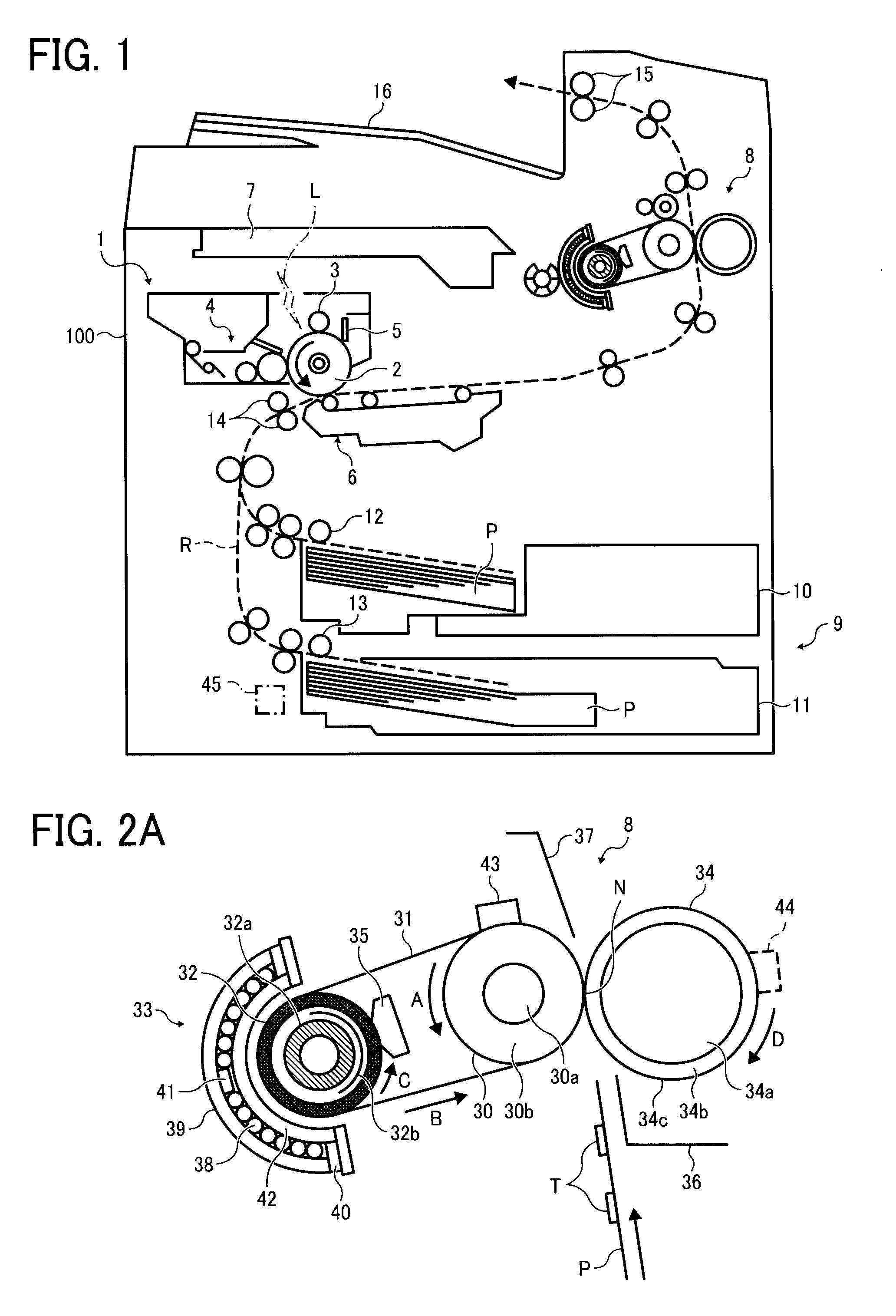
[0094]More specifically, the fixing device 8A includes a thermistor 44, represented by a dashed square depicted in FIGS. 2A and 2B, functioning as the pressing member temperature detector disposed in contact with a part of the outer circumferential surface of the pressure roller 34. Alternatively, as for the p...
third embodiment
[0111]Next, a fixing device 8B according to a third embodiment is described below. It is to be noted, that the basic operation of fixing device 8B is similar to the operational process in the flow chart shown in FIG. 4. Additionally, other than the difference described below the fixing device 8B has components similar to the component of the fixing device 8A which are represented by identical reference numerals, and therefore a description thereof is omitted for simplicity.
[0112]The fixing device 8B includes the pressing member temperature detector similarly to the second embodiment. However, additionally, the fixing device 8B includes an ambient-temperature detector that detects the ambient temperature of the environmental around the sheet. As for the ambient-temperature detector, an ambient-temperature sensor 45 that is disposed closer to the sheet cassette 11, represented as an alternate long and short dashed square depicted in FIGS. 1 and 2B, can be used. The ambient-temperature...
PUM
 Abstract
Description
Claims
Application Information
 - Generate Ideas
- Intellectual Property
- Life Sciences
- Materials
- Tech Scout
- Unparalleled Data Quality
- Higher Quality Content
- 60% Fewer Hallucinations
Browse by: Latest US Patents, China's latest patents, Technical Efficacy Thesaurus, Application Domain, Technology Topic, Popular Technical Reports.
© 2025 PatSnap. All rights reserved.Legal|Privacy policy|Modern Slavery Act Transparency Statement|Sitemap|About US| Contact US: help@patsnap.com