Photovoltaic solar panel mounting system

a solar panel and solar panel technology, applied in the direction of heat collector mounting/support, building repair, lighting and heating apparatus, etc., can solve the problems of difficult adjustment or replacement, no convenient way to remove,

Inactive Publication Date: 2010-09-23
TWEEDIE RICHARD
View PDF4 Cites 52 Cited by
  • Summary
  • Abstract
  • Description
  • Claims
  • Application Information

AI Technical Summary

Problems solved by technology

If a failed module is in the middle of a large array, there is no convenient way to remove it.
Panel grounding represents a significant portion of the time required to install a solar array.
Also, mechanical tying of panels makes any subsequent adjustment or replacement quite difficult.

Method used


Image

  • Photovoltaic solar panel mounting system
  • Photovoltaic solar panel mounting system
  • Photovoltaic solar panel mounting system

Examples


Embodiment Construction

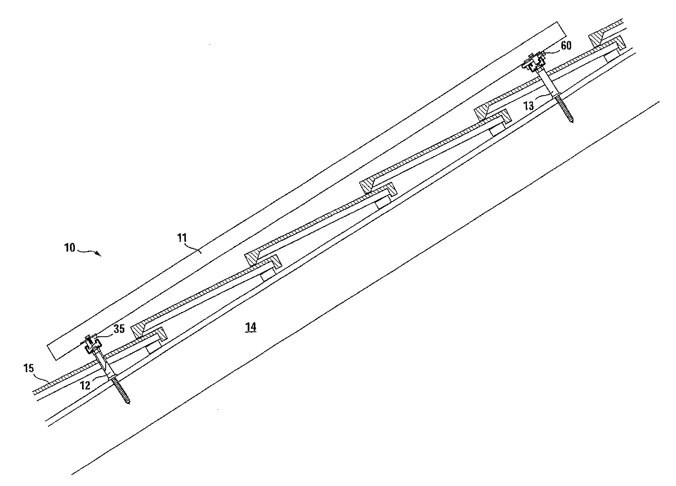
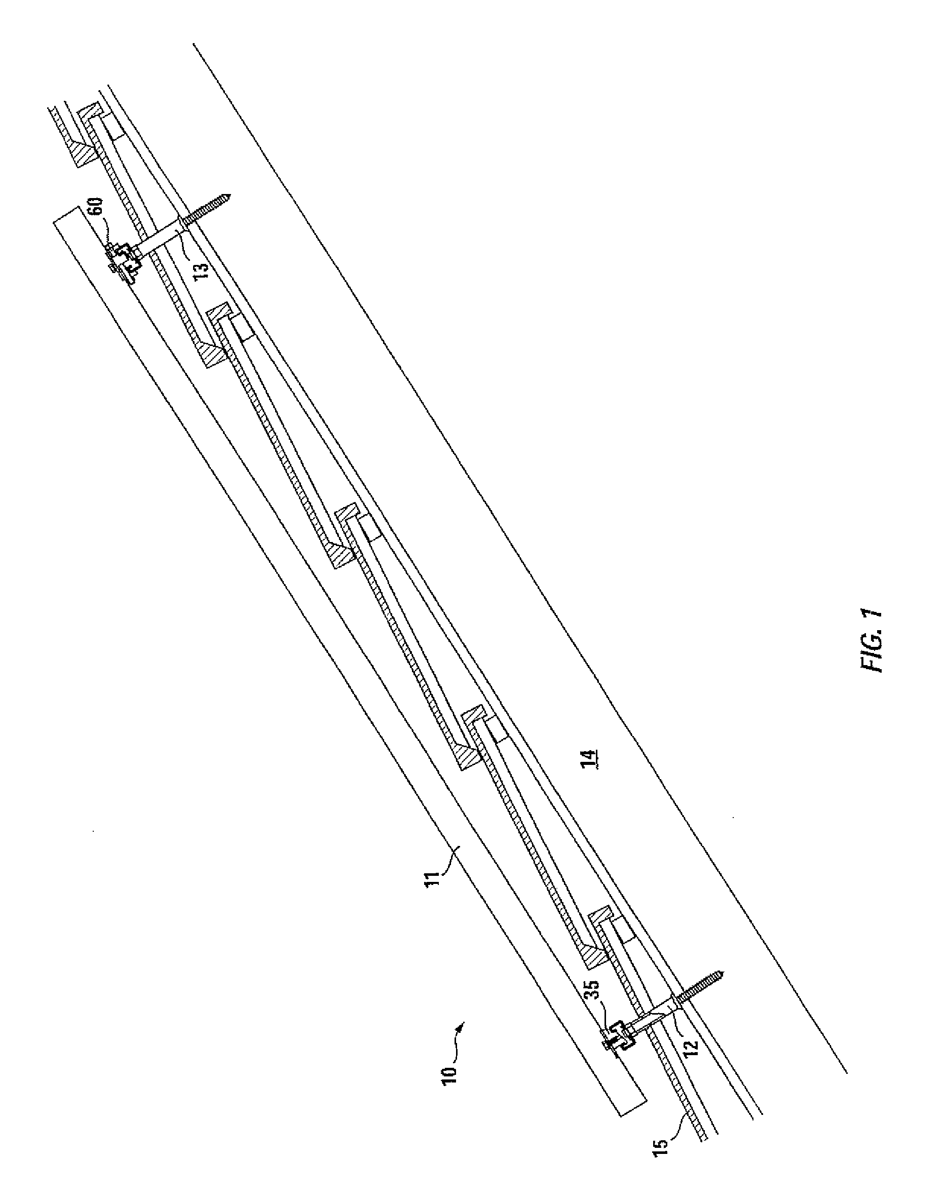
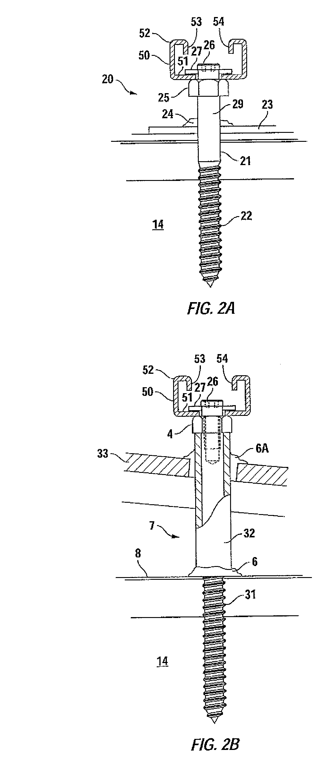
[0024]The present invention involves system 10 for mounting photovoltaic solar panel 11 onto a roof. Mounting is generally carried out by providing standoffs best visualized by reference to FIGS. 2A and 2B.

[0025]Turning first to FIG. 2A, standoff 20 is in the form of threaded bolt 21 having a series of threads 22 which, upon installation, are embedded within rafter 14. FIG. 2A is specifically illustrative of a standoff used on a composite roof whereby composite roof surface 23 is penetrated by bolt 21 and sealant 24, such as Geocel 2300 Tripolymer, employed to prevent water intrusion below composite roof surface 23.

[0026]As noted, bolt 21 has shaft 29 of sufficient length as to space strut rail 50 from composite roof surface 23. As strut rail 50 will act to support the appropriate photovoltaic solar panel 11, the standoff height of head 25 of lag screw 21 is such that photovoltaic solar panel 11 will be provided with appropriate ventilation. This is best seen in FIG. 1 noting stando...


PUM


Abstract

A system and method for mounting photovoltaic solar panels onto a roof. The system includes first and second strut rails spaced from the roof employing a series of standoffs, the strut rails having a length, cross section, a base and side walls, side walls terminating with first and second turned in edges. First and second mounting fixtures are attached to the photovoltaic solar panels which are of a type and geometry enabling the solar panels to be removably appended to the strut rails. The first and second mounting fixtures can be applied to the photovoltaic solar panels before being elevated to a roof.

Description

RELATED APPLICATION DATA[0001]The present application is a continuation in part of U.S. application Ser. No. 12 / 407,952, filed on Mar. 20, 2009, now abandoned.TECHNICAL FIELD[0002]The present invention is directed to a system for mounting photovoltaic solar panels onto a roof in a safer, more expedient and efficient manner than has previously been possible. The present system includes self-grounding hardware much of which can be installed on the photovoltaic solar panels prior to elevating them to a roof top location thus dramatically increasing the safety factor of such an installation.BACKGROUND OF THE INVENTION[0003]Virtually all roof top solar installations involve the elevation and securement of photovoltaic solar panels that are fixed in place by standoffs that penetrate the roof to tie the installation into structural rafters. Horizontally aligned rails hold the panels off of a roof to allow cooling ventilation to their undersides while providing points of attachment for the ...

Claims


Application Information

Patent Timeline
Patent Type & Authority Applications(United States)
IPC IPC(8): E04D13/18E04B1/61E04B1/38
CPCF24J2/5203F24J2/5245F24J2/5254F24J2002/4661H02S20/23Y02B10/12Y02B10/20Y02E10/47F24J2002/4667F24S25/30F24S25/61F24S25/632F24S2025/6002F24S2025/6005Y02B10/10Y02E10/50
Inventor TWEEDIE, RICHARD
Owner TWEEDIE RICHARD
Why Eureka
Try Eureka