Laser energy source device and method

Active Publication Date: 2010-09-23
STUART MARTIN A
View PDF15 Cites 16 Cited by
  • Summary
  • Abstract
  • Description
  • Claims
  • Application Information

AI Technical Summary

Benefits of technology

[0009]Also provided is a suggested design that would allow for a forty percent or higher on target d

Problems solved by technology

Laser diode power modules are known to change their peak output frequency with temperature variants, which naturally occur in arrays of laser diodes, typically at a rate of 0.3 nanometers per degree C. This often causes the entire array to operate at different frequencies from the point of turn-on until they have reached overload, with potentially negative results.
This results in a corresponding color output difference in commercially available diode laser stacks or mo

Method used


Image

  • Laser energy source device and method
  • Laser energy source device and method
  • Laser energy source device and method

Examples


Embodiment Construction

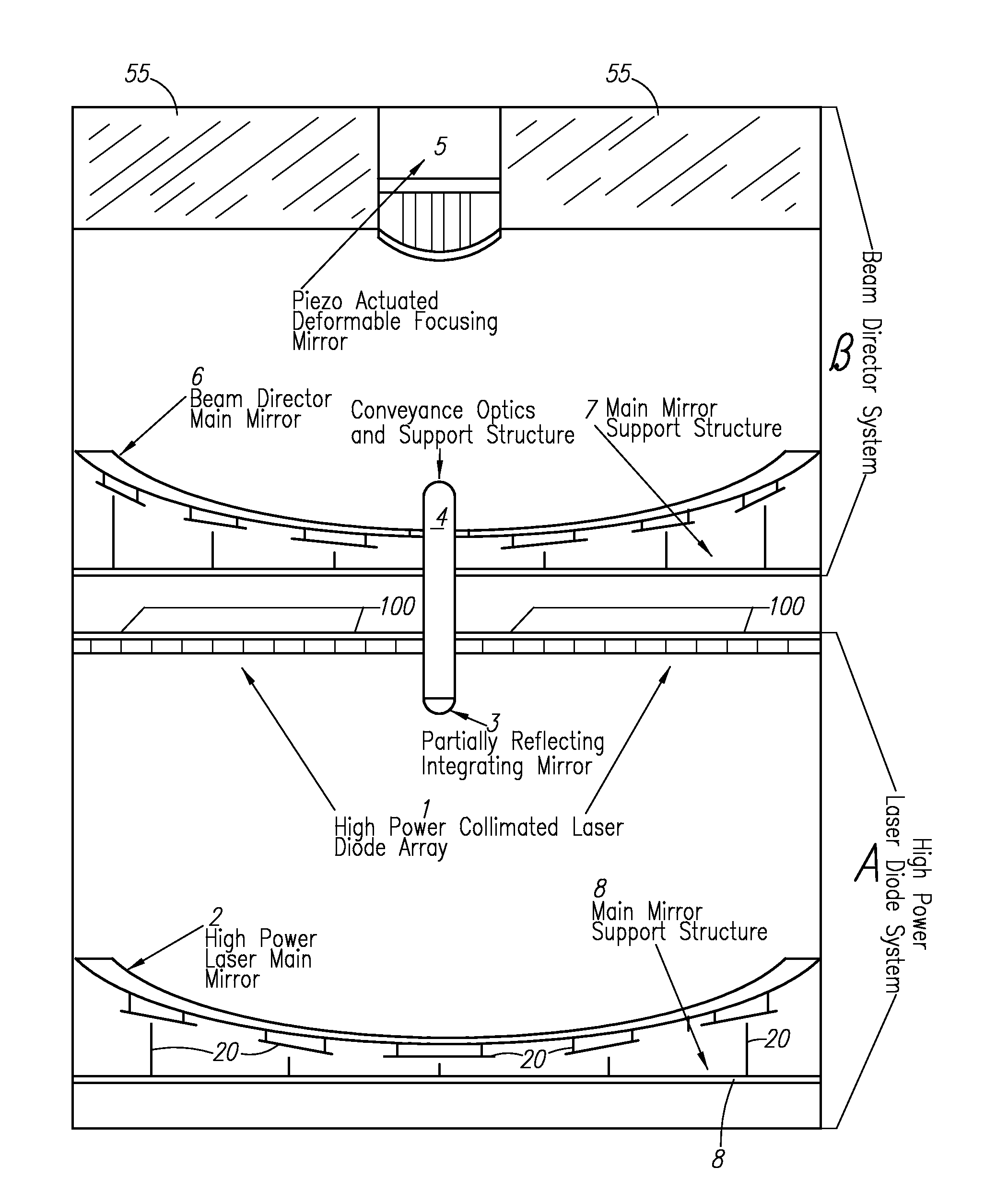
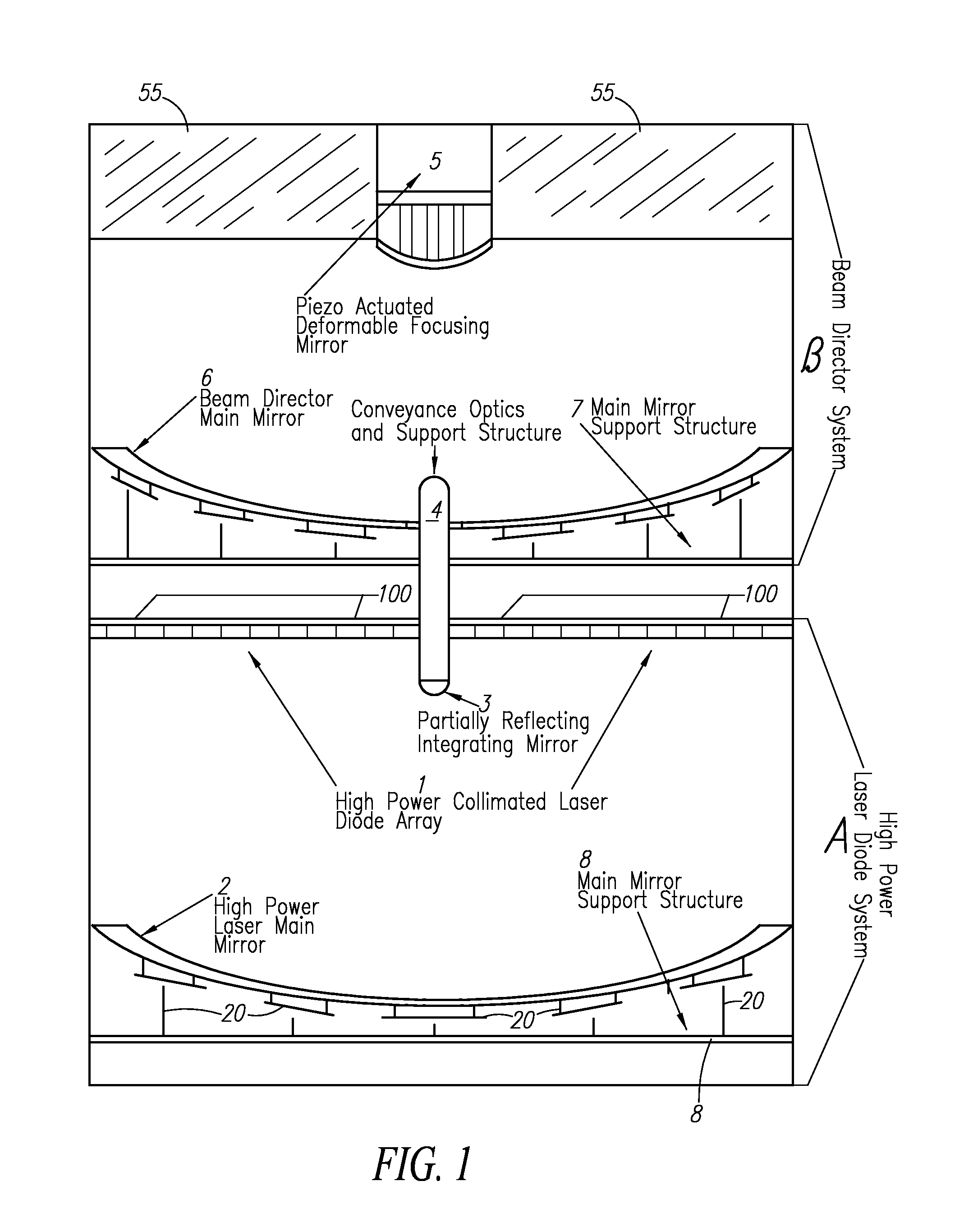
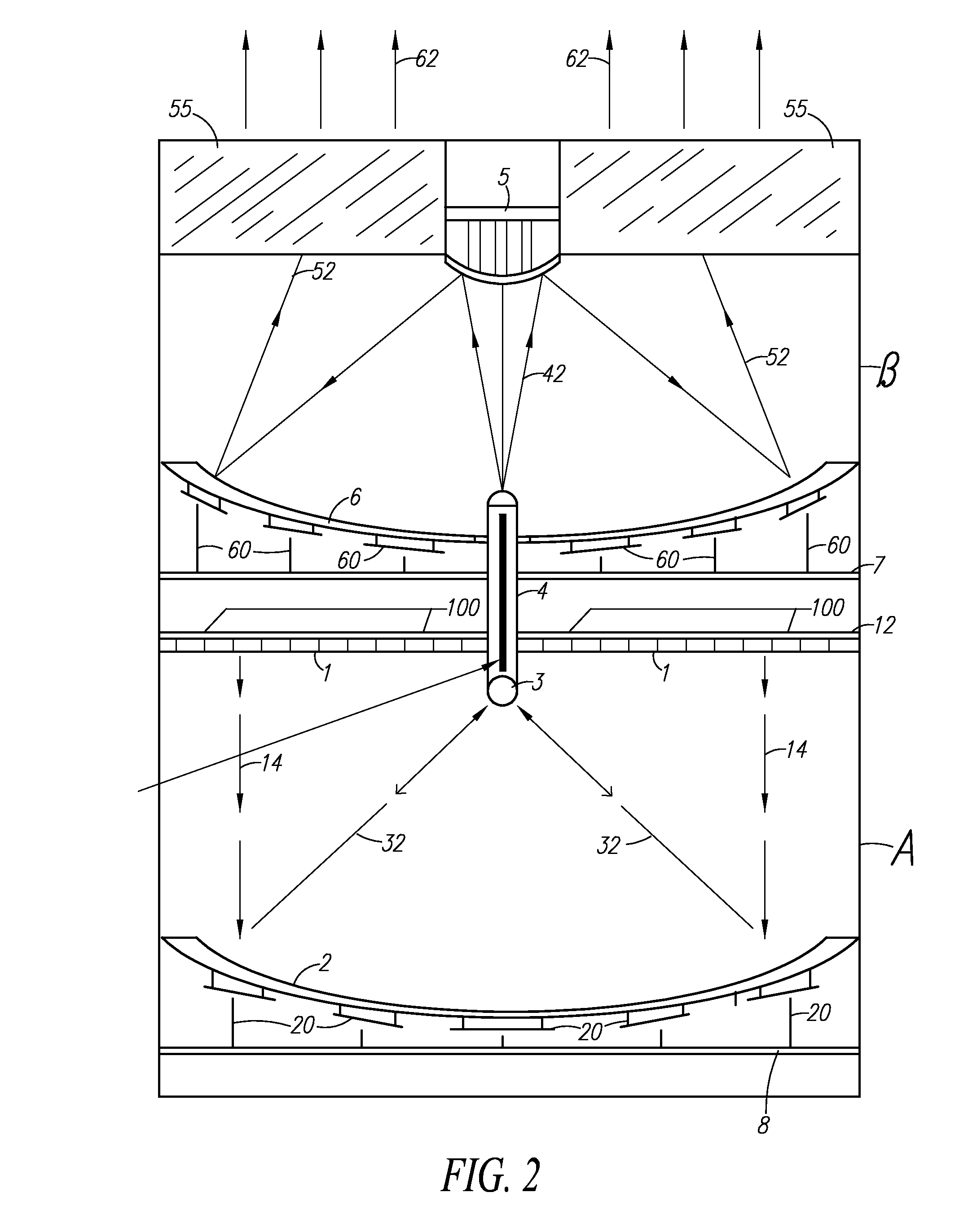
[0024]This application describes embodiments of a device (or system of devices / components) and a method that can allow power scaling to just about any level desired, from lower power applications to high-power applications, for arrays of various laser emitters. The beam provided by use of these devices / methods will be of a single wavelength and coherence length, which makes it very useful and adaptable.

[0025]To create such a system, diode laser power bars can be utilized. Such diode bars are high-power semiconductor lasers (laser diodes), containing a one-dimensional array of broad-area emitters. They typically contain between 20 and 50 emitters, each being e.g. 100 μm wide. The diode laser power bars are then fabricated into stacked arrays, such as, for the purpose of illustration, 2 cm wide×a chosen length, but other dimensions can be used where appropriate for the given application. For the purposes of an example used in this application, a fabricated size of 2 cm wide×5 cm high ...


PUM


Abstract

An innovative device and method for providing a laser system utilizing high efficiency diode lasers and optionally the high quality beam characteristics of a crystal gain medium single mode laser by utilizing an optical and mechanical method of forming the beam and directing it to the desired target.

Description

CROSS-REFERENCES TO RELATED APPLICATIONS[0001]This application claims the benefit of co-pending U.S. provisional application Ser. No. 61 / 000,228, filed on Oct. 25, 2007, incorporated herein by reference.BACKGROUND OF THE INVENTION[0002]Lasers have various applications. The determination of any particular application is dependent on both the power and the beam characteristics. Pulse length, energy per pulse, polarization, and coherence length all play a part in the final outcome of the chosen application. Although there are many different types of lasers, as well as many different applications, of particular usefulness for many applications are diode lasers.[0003]Diode lasers have high electrical efficiency and can be set up in an array pattern which can then be scaled to produce a high power. In the past, when such an arrangement was attempted, each emitter (usually 1 of 50 per cm bar, put into a stack) has produced a beam with a separate, differing wavelength (i.e.: color), coheren...

Claims


Application Information

Patent Timeline
IPC IPC(8): G02B6/04F21V1/00
CPCH01S5/005H01S5/4062H01S5/4025H01S5/4012
Inventor STUART, MARTIN A.
Owner STUART MARTIN A
Why Eureka
Try Eureka