
Laser energy source device

a laser energy source and laser technology, applied in the direction of fixed installation, lighting and heating apparatus, instruments, etc., can solve the problems of not producing useful, affecting the usefulness of diode lasers for a number of useful applications, and corresponding color output differences in commercially available diode laser stacks or modules

Inactive Publication Date: 2015-02-10
STUART MARTIN A
View PDF24 Cites 2 Cited by
  • Summary
  • Abstract
  • Description
  • Claims
  • Application Information

AI Technical Summary

Benefits of technology

The patent describes a design for a device that can deliver electrical energy to light energy with a high degree of accuracy and at a low cost for military applications.

Problems solved by technology

Laser diode power modules are known to change their peak output frequency with temperature variants, which naturally occur in arrays of laser diodes, typically at a rate of 0.3 nanometers per degree C. This often causes the entire array to operate at different frequencies from the point of turn-on until they have reached overload, with potentially negative results.
This results in a corresponding color output difference in commercially available diode laser stacks or modules.
This can be a particular problem if the laser is to be focused miles, hundreds of miles, or thousands of miles away.
This has limited the usefulness of diode lasers for a number of useful applications, including high-power applications.
The prior art diode lasers have not produced a useful, simple to implement, single output beam device, and such a result has eluded the scientific and technology worlds.
But none of these solutions are adequate for all current needs.

Method used


Image

  • Laser energy source device
  • Laser energy source device
  • Laser energy source device

Examples


Embodiment Construction

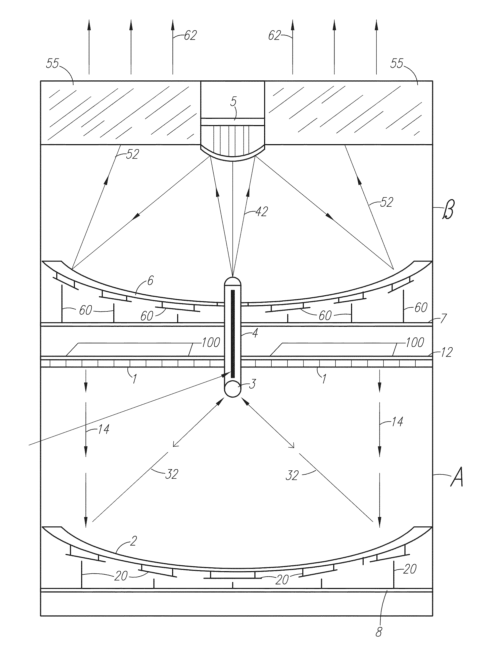
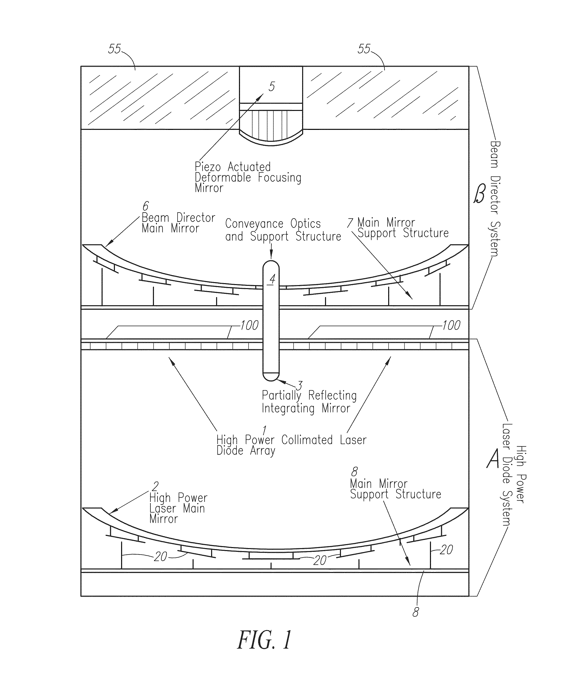
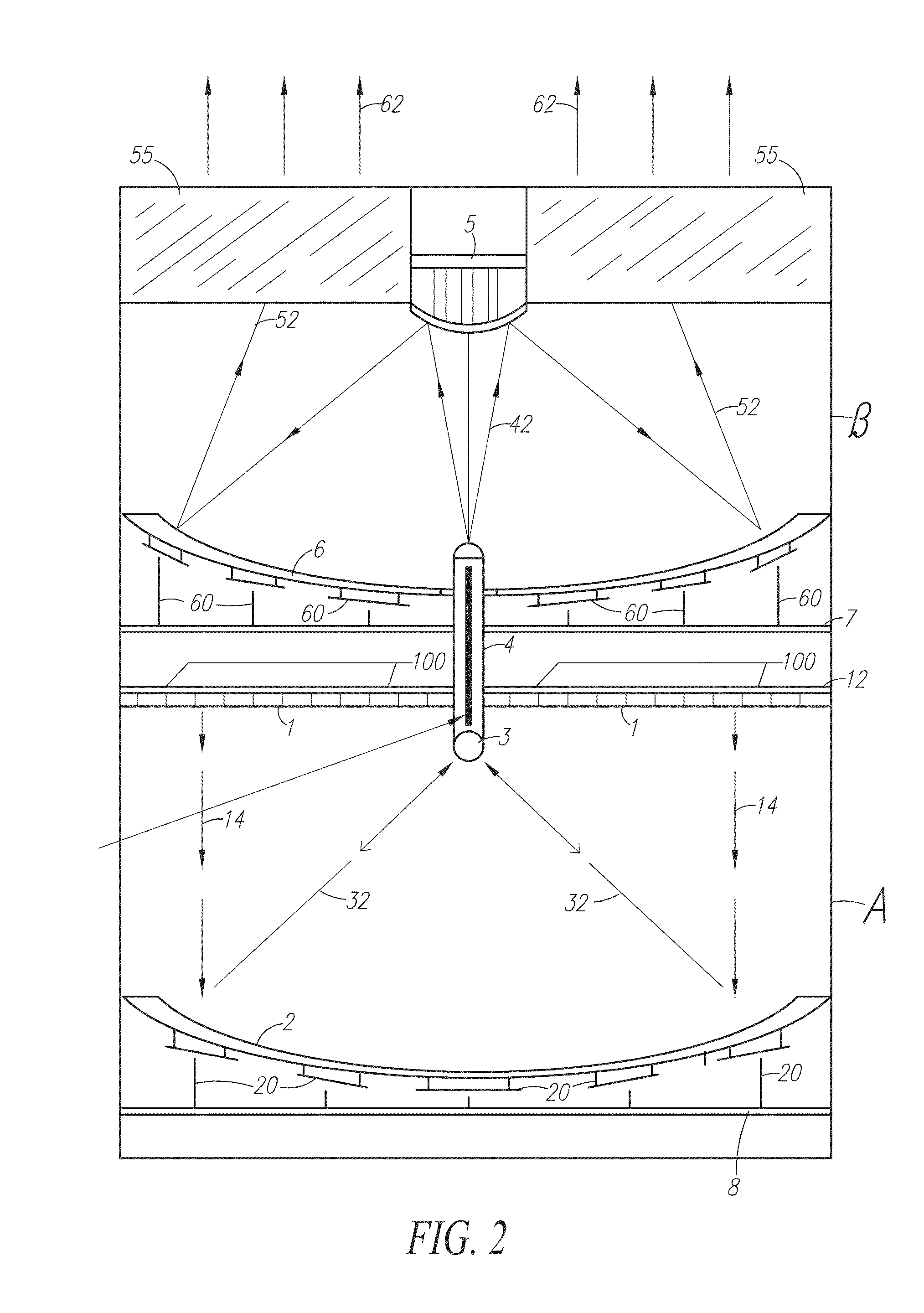
[0029]This application describes various embodiments of a device (or system of devices / components) and a method that can allow power scaling to just about any level desired, from lower power applications to high-power applications, for arrays of various laser emitters. In particular is disclosed an Integrating Feedback Mirror (IFM) system for focusing and aligning laser beams (beamlets) The beam(s) provided by use of these devices / methods may be of a single wavelength and coherence length, which makes it very useful and adaptable.

[0030]A number of emitter and / or different gain materials can be used effectively with this IFM system. One example emitter is based on diode laser gain materials. The operating principle of this system is that any optically active gain system within the diameter of the main mirror and its expanded and collimated injection seed laser beam, will be integrated into a more controlled beam output system with a line narrowed output, after passing through a frequ...


PUM


Abstract

A device and method for providing a laser system utilizing high efficiency lasers emitters and optionally the high quality beam characteristics of a crystal gain medium single mode laser for emitting beamlets and utilizing an optical and mechanical method of forming the beam and directing it to the desired target using both a concave and a partially reflective convex mirror to reflect the beamlets, with the convex mirror transmitting a portion of the beamlets to a transmission medium for emitting the beamlets as a laser beam.

Description

CROSS-REFERENCES TO RELATED APPLICATIONS[0001]This application is a continuation-in-part of U.S. Pat. No. 8,439,523 filed on May 23, 2012, which is a continuation of U.S. Pat. No. 8,220,965 that was filed on Apr. 20, 2010, that was a continuation of PCT application serial number PCT / US08 / 81137 filed on Oct. 24, 2008, and which claims the benefit of U.S. provisional application Ser. No. 61 / 000,228, filed on Oct. 25, 2007, all incorporated herein by reference.BACKGROUND OF THE INVENTION[0002]Lasers have various applications. The determination of any particular application is dependent on both the power and the beam characteristics. Pulse length, energy per pulse, polarization, and coherence length all play a part in the final outcome of the chosen application. Although there are many different types of lasers, as well as many different applications, of particular usefulness for many applications are diode lasers.[0003]Diode lasers have high electrical efficiency and can be set up in a...

Claims


Application Information

Patent Timeline
Patent Type & Authority Patents(United States)
IPC IPC(8): G02B27/20G02B19/00H01S5/00H01S5/065
CPCH01S5/0071H01S5/0656G02B19/0057G02B19/0023G02B19/0052H01S3/06754H01S3/09415H01S3/2383H01S5/005H01S5/4012H01S5/4025H01S5/02325
Inventor STUART, MARTIN A.
Owner STUART MARTIN A
Learn More