
Airflow restriction system

a technology of airflow restriction and patient, which is applied in the field of patient apparatus and methods for controlling airflow through nasal passages of patients, can solve the problems of user wear, many patients have difficulty in adjusting to cpap devices, and cannot be done while the patient, so as to facilitate fluid transfer and restrict airflow through the patient's nasal passages

Inactive Publication Date: 2010-09-23
LI KASEY K
View PDF49 Cites 23 Cited by
  • Summary
  • Abstract
  • Description
  • Claims
  • Application Information

AI Technical Summary

Benefits of technology

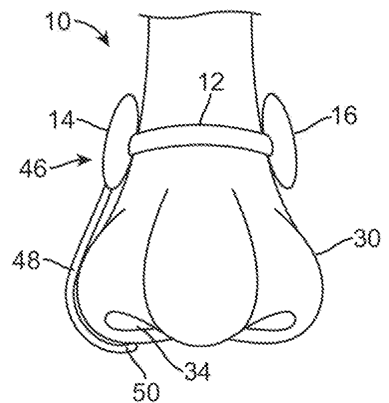
[0016]In another example, a fluid or gas may be actuated between a reservoir and inflatable respective first and second restriction elements to partially constrict the airflow through the patient's nasal passages. A fluid lumen may connect the reservoir with the restriction elements and the first and / or second actuatable members may be positioned alone a surface or within the reservoir such that when the actuatable members are actuated to squeeze or constrict, the fluid contained within the reservoir may be forced or urged out and into the respective first and second inflated restriction members such that inflation of these members constrict the underlying nasal passages to induce the expiratory positive airway pressure. During inhalation, the actuatable members may be relaxed to allow the fluid to flow back from the members into the reservoir. To facilitate the fluid transfer, the members may be made from a distensible material, such as latex, which may be inflated yet is biased to collapse to urge the fluid back into the reservoir.

Problems solved by technology

However, such pulmonary rehabilitation exercises require that the patient consciously perform them and they cannot be done while the patient is asleep.
However, many patients have difficulties in adjusting to CPAP devices for various reasons.
However, such devices requiring securement, e.g., within the nostrils, may be uncomfortable for the user to wear and may also provide a poor fit depending upon the anatomy of the patient's nasal passages.

Method used


Image

  • Airflow restriction system
  • Airflow restriction system
  • Airflow restriction system

Examples


Embodiment Construction

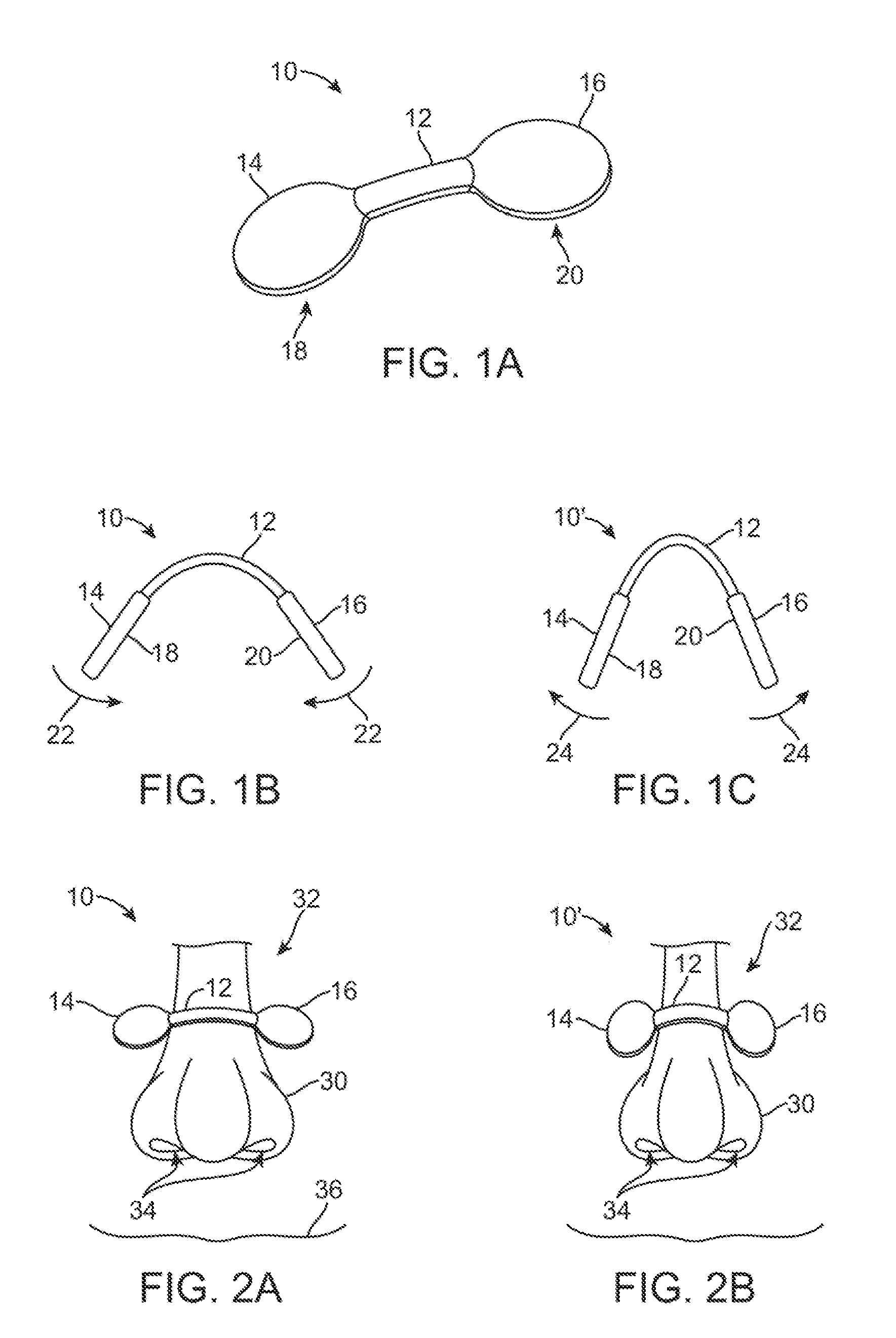
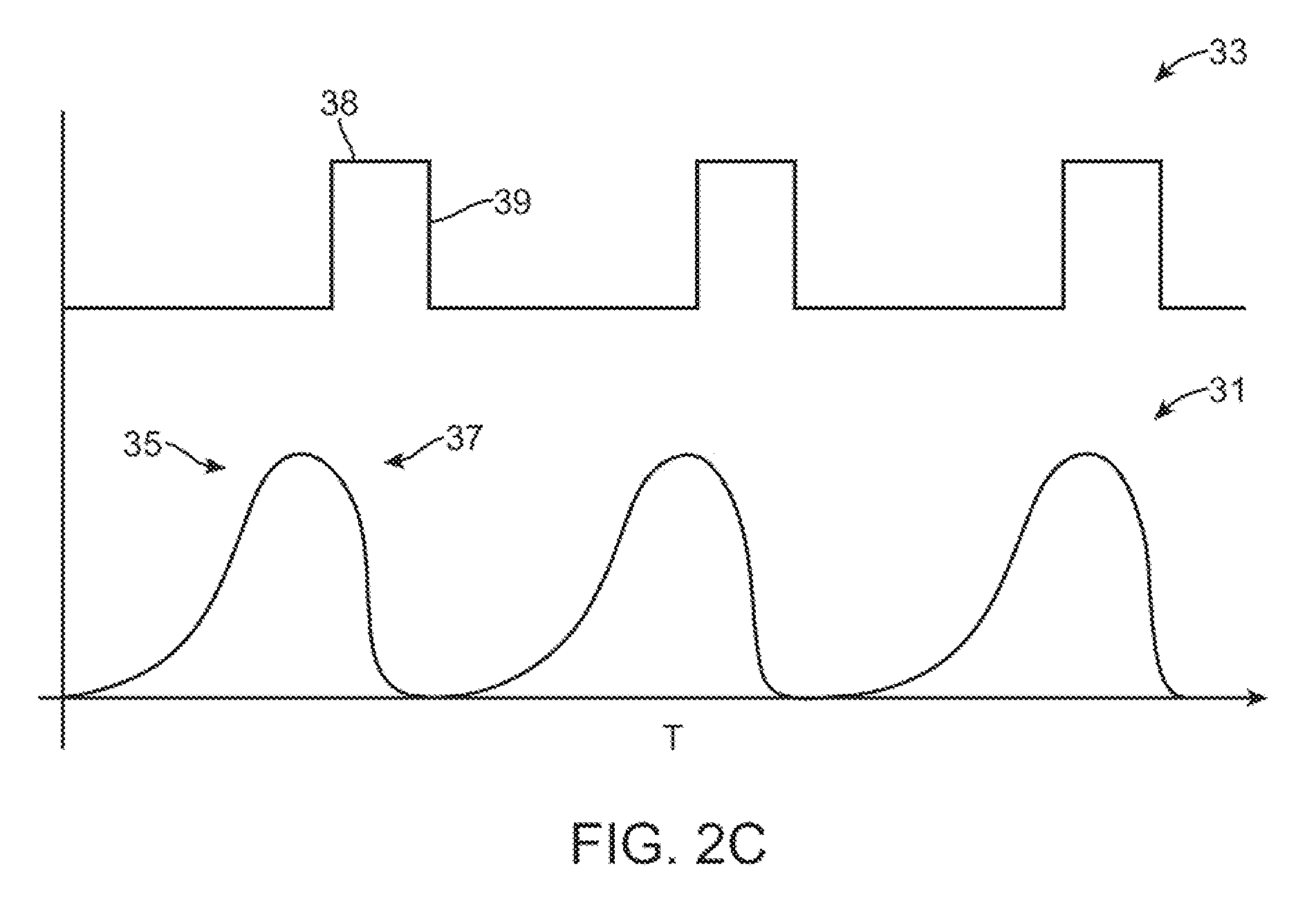
[0033]In treating various disorders, e.g., snoring, OSA, COPD, asthma, heart failure, etc., a device which can create expiratory positive airway pressure may be utilized which provides for patient comfort regardless of the patient's anatomical variances. Generally, such a device may be optionally disposable and may be removably secured extenially over the patient's nose rather than within the nasal passages to increase patient comfort. The restriction device may be secured, e.g., via an adhesive, to the patient and actuated via any number of mechanical or electromechanical mechanisms. Moreover, the restriction device may include one or more sensors to detect the patient's respiration activity such that the device may be actuated to correspond to the patient's exhalation and squeeze or otherwise constrict the nasal passages at least partially by pressing against the exterior surface of the nose to restrict the expiratory airflow.

[0034]As shown in the perspective view of FIG. 1A, one ...


PUM


Abstract

Airflow restriction systems are described herein which may be used to treat various disorders by creating expiratory positive airway pressure while providing for patient comfort regardless of the patient's anatomical variances. Such a device may be removably secured externally over the patient's nose rather than within the nasal passages to increase patient comfort. The restriction device may be secured, e.g., via an adhesive, to the patient and actuated via any number of mechanical or electromechanical mechanisms. Moreover, the restriction device may include one or more sensors to detect the patient's respiration activity Such that the device may be actuated to correspond to the patient's exhalation and squeeze or otherwise constrict the nasal passages at least partially by pressing against the exterior surface of the nose to restrict the expiratory airflow.

Description

FIELD OF THE INVENTION[0001]The present invention relates to apparatus and methods for controlling airflow through nasal passages of a patient. More particularly, the present invention relates to methods and apparatus for controllably restricting airflow through the nasal passages of the patient for the treatment of various disorders such as snoring, obstructive sleep apnea (OSA), chronic obstructive pulmonary disease (COPD), asthma, heart failure, etc.BACKGROUND OF THE INVENTION[0002]In treating various disorders such as snoring, OSA, COPD, asthma, heart failure, etc., therapies such as pulmonary rehabilitation or mechanical ventilation are typically employed. Pulmonary rehabilitation generally involves educating the patient and having them perform various exercises to reduce symptoms and to decreases the disability by helping to condition pulmonary muscles and increase inspiratory tidal volumes. However, such pulmonary rehabilitation exercises require that the patient consciously ...

Claims


Application Information

Patent Timeline
Patent Type & Authority Applications(United States)
IPC IPC(8): A61F5/08
CPCA61F5/08
Inventor LI, KASEY K.
Owner LI KASEY K
Learn More