Spacecraft heat dissipation system

Active Publication Date: 2010-09-30
LOCKHEED MARTIN CORP
View PDF19 Cites 39 Cited by
  • Summary
  • Abstract
  • Description
  • Claims
  • Application Information

AI Technical Summary

Problems solved by technology

For many GEO satellites, the capacity of these north/south thermal radiators is a key design driver that often serves to limit the overall satellite's capacity.
Differential solar illumination as a function of inclination of the earth's ax

Method used


Image

  • Spacecraft heat dissipation system
  • Spacecraft heat dissipation system
  • Spacecraft heat dissipation system

Examples


Embodiment Construction

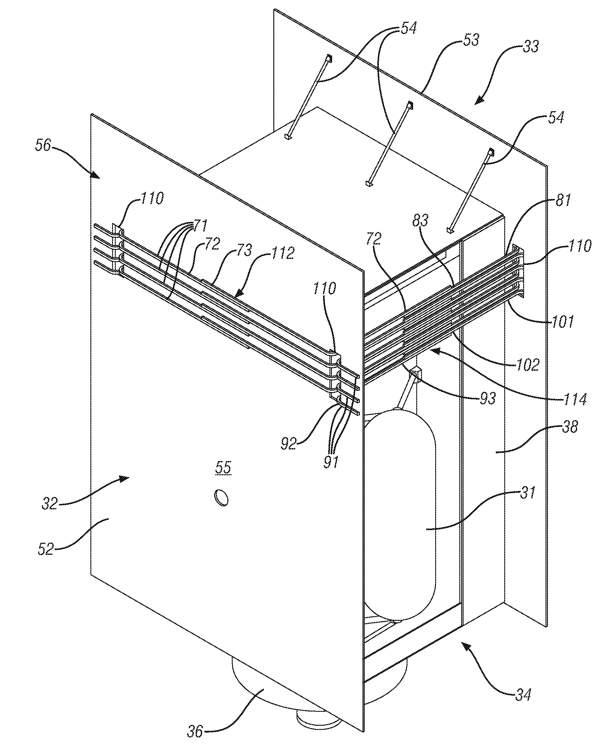
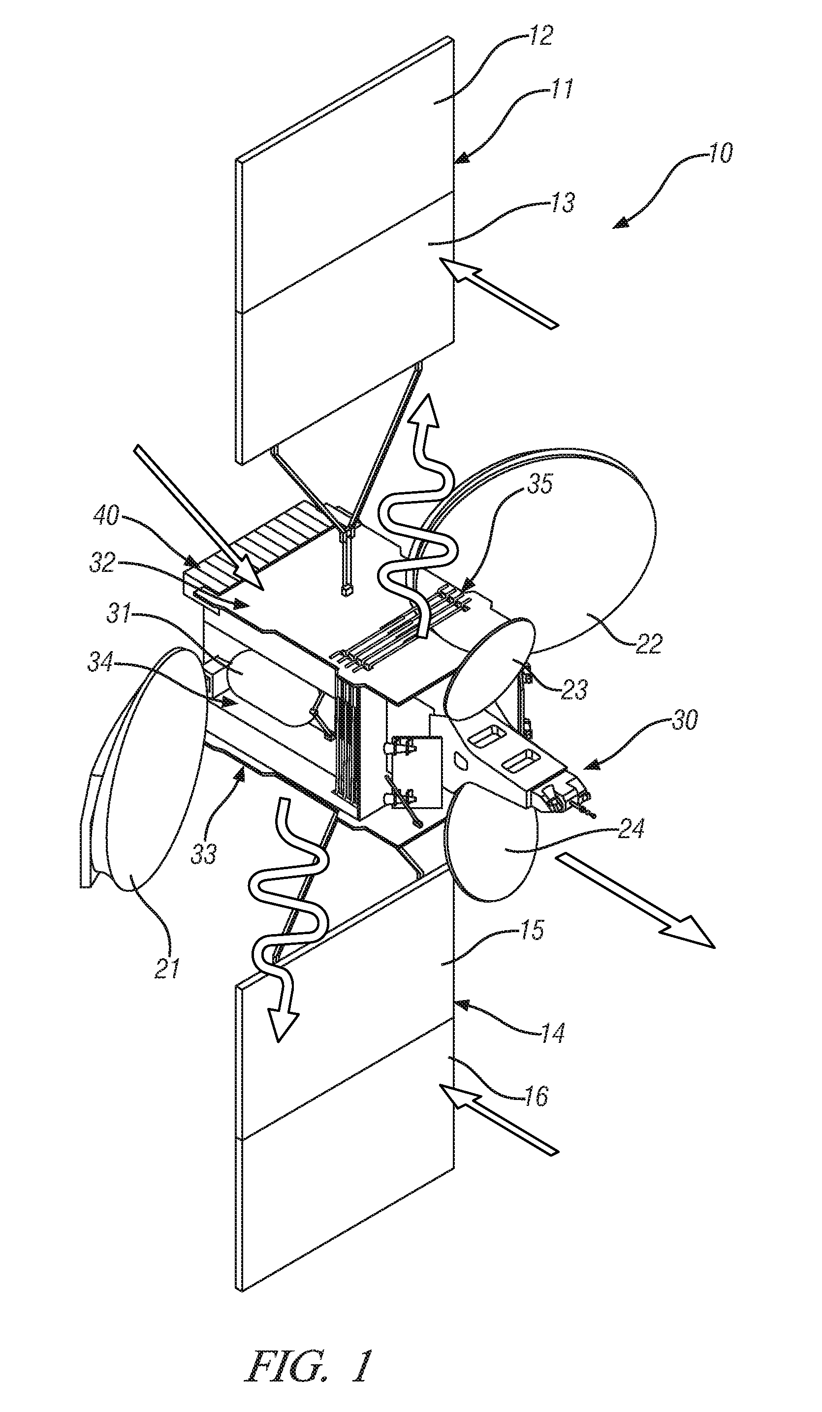
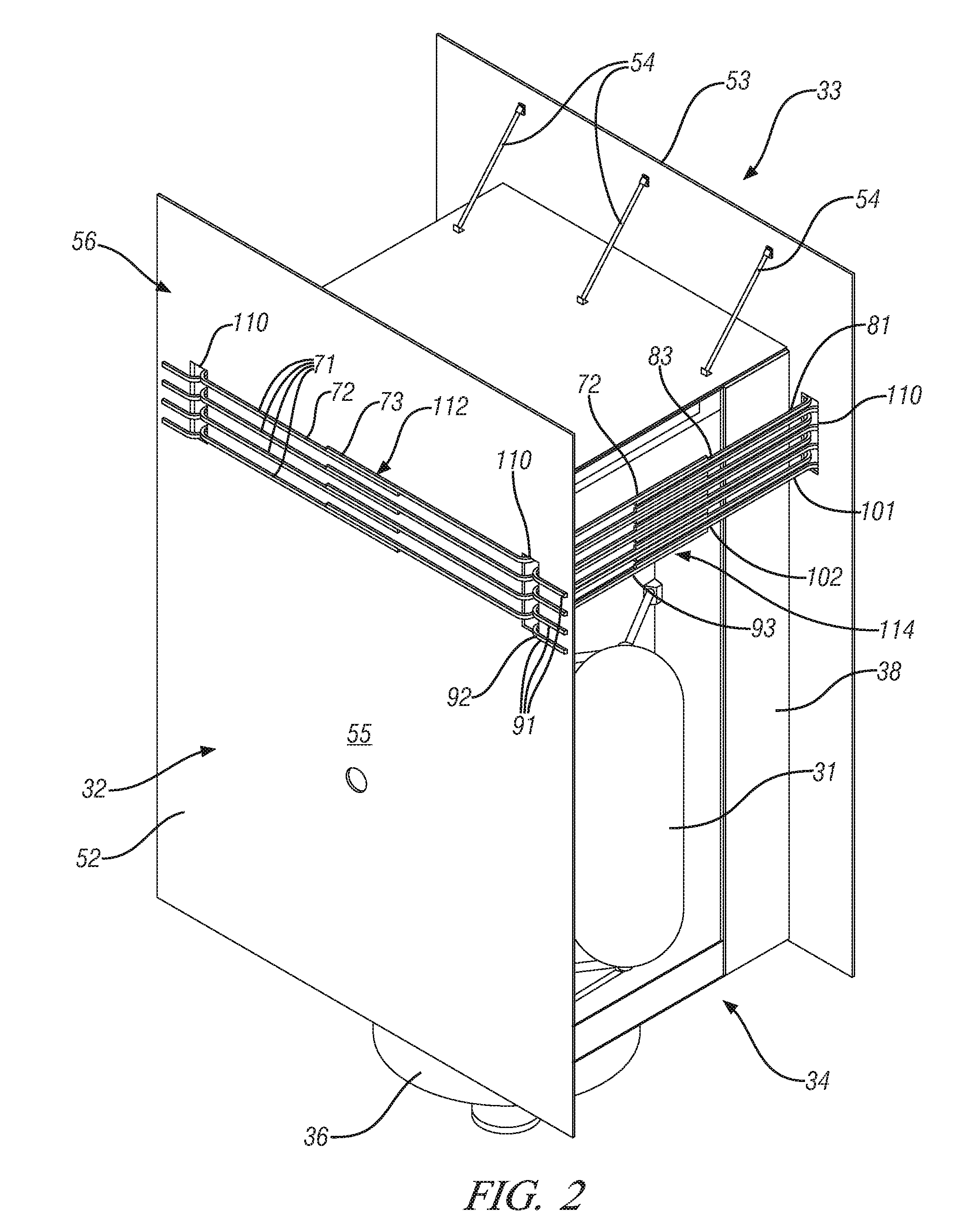
[0022]Referring now to the Figures, where the invention will be described with reference to specific embodiments, without limiting same, FIG. 1 shows a spacecraft or satellite 10 in accordance with the invention. In the exemplary embodiment shown, spacecraft 10 is a communications satellite configured for geostationary orbit around the earth. As such, spacecraft 10 is configured to maintain a generally constant orientation relative to the earth as it orbits about the earth. The following detailed description will describe certain elements of spacecraft 10 relative to each other by reference to direction on the earth. However, the nomenclature used is for convenience only and is not intended to be limiting to direction. It will be appreciated that like elements are described with like numerals throughout this disclosure. Where alternate embodiments of like elements are shown, a prefix numeral may be added to distinguish the element from alternate embodiments.

[0023]Spacecraft 10 inclu...


PUM


Abstract

A spacecraft is provided. The spacecraft comprises a plurality of heat generating electrical components. A first thermal radiator panel and a second thermal radiator panel are provided on the spacecraft, each panel being thermally coupled to the heat generating electrical components. Heat pipes are also provided. At least one first heat pipe is externally attached to the first thermal radiator panel and at least one second heat pipe is externally attached to the second thermal radiator panel. The at least one first heat pipe is thermally coupled to the at least one second heat pipe.

Description

CROSS-REFERENCE TO RELATED APPLICATIONS[0001]This patent application claims priority to U.S. Provisional Patent Application Ser. No. 61 / 162,995, filed Mar. 24, 2009 which is incorporated herein by reference in its entirety.BACKGROUND OF THE INVENTION[0002]The present disclosure relates to satellites and more particularly to an improved waste heat removal system for spacecraft, including satellites.[0003]The thermal control systems used in geostationary satellites (satellites using a geosynchronous orbit and commonly referred to as GEO satellites) typically rely on north and south facing panels to reject most of their waste heat and maintain thermal balance. For many GEO satellites, the capacity of these north / south thermal radiators is a key design driver that often serves to limit the overall satellite's capacity. Consequently, improvements in the efficiency of these heat removal systems can significantly improve overall satellite design capabilities and capacity. Furthermore, in o...

Claims


Application Information

Patent Timeline
IPC IPC(8): B64G1/58
CPCB64G1/50B64G1/506B64G1/503F28D15/0275
Inventor MCKINNON, DOUGLAS V.MORAN, TIMOTHY P.
Owner LOCKHEED MARTIN CORP
Why Eureka
Try Eureka