

Mechanical jig
- Summary
- Abstract
- Description
- Claims
- Application Information
AI Technical Summary
Benefits of technology
Problems solved by technology
Method used
Image

Examples
Embodiment Construction
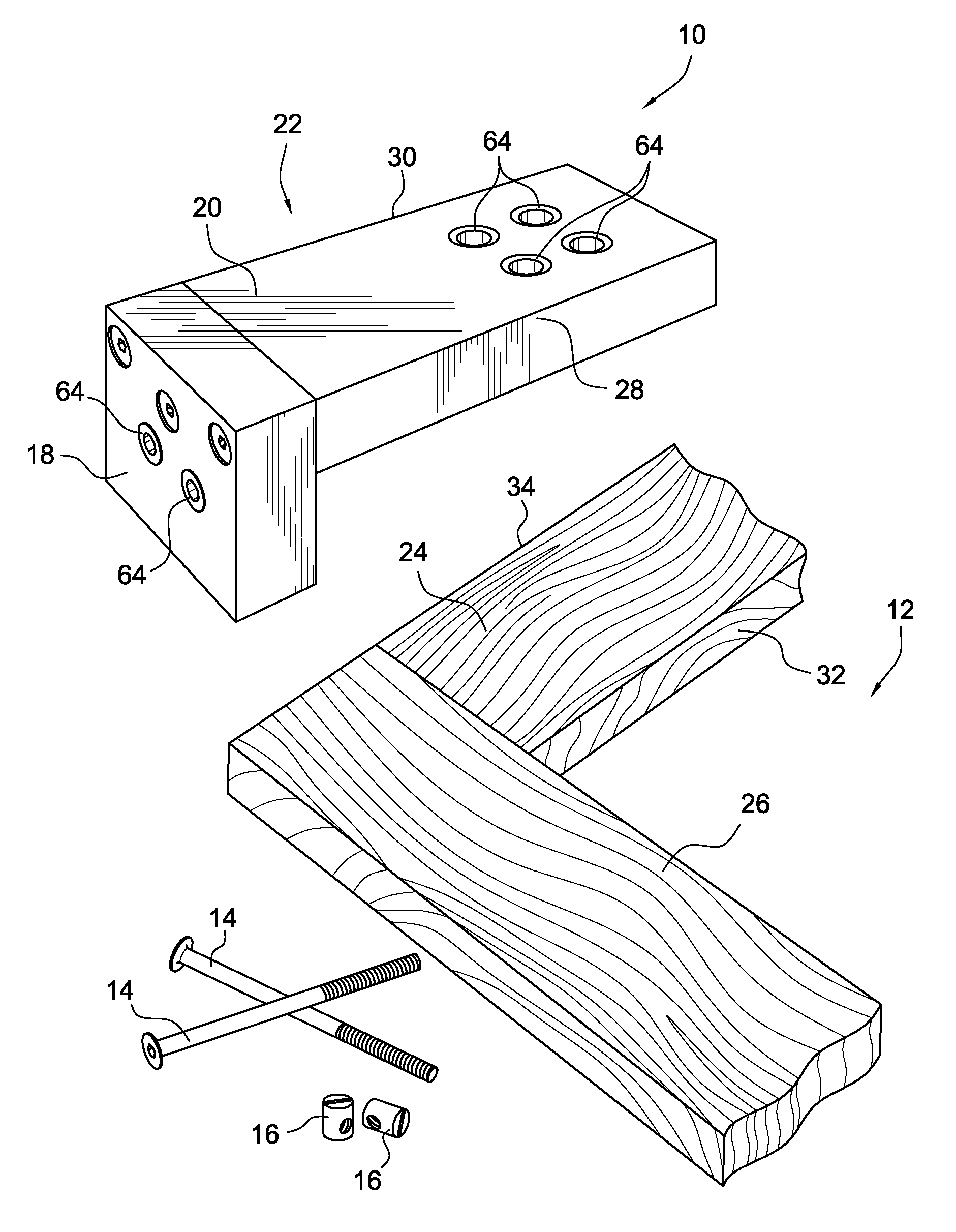
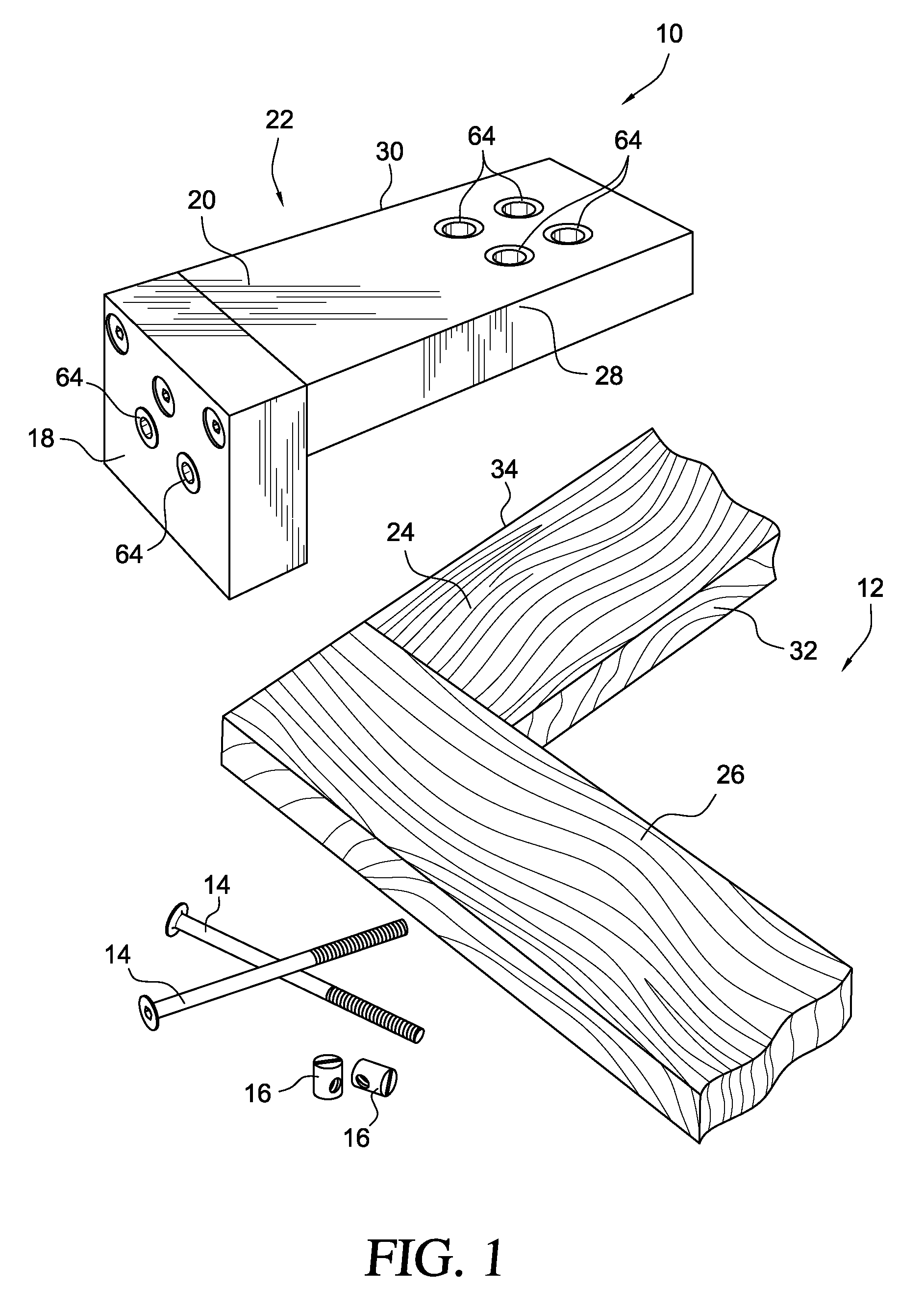
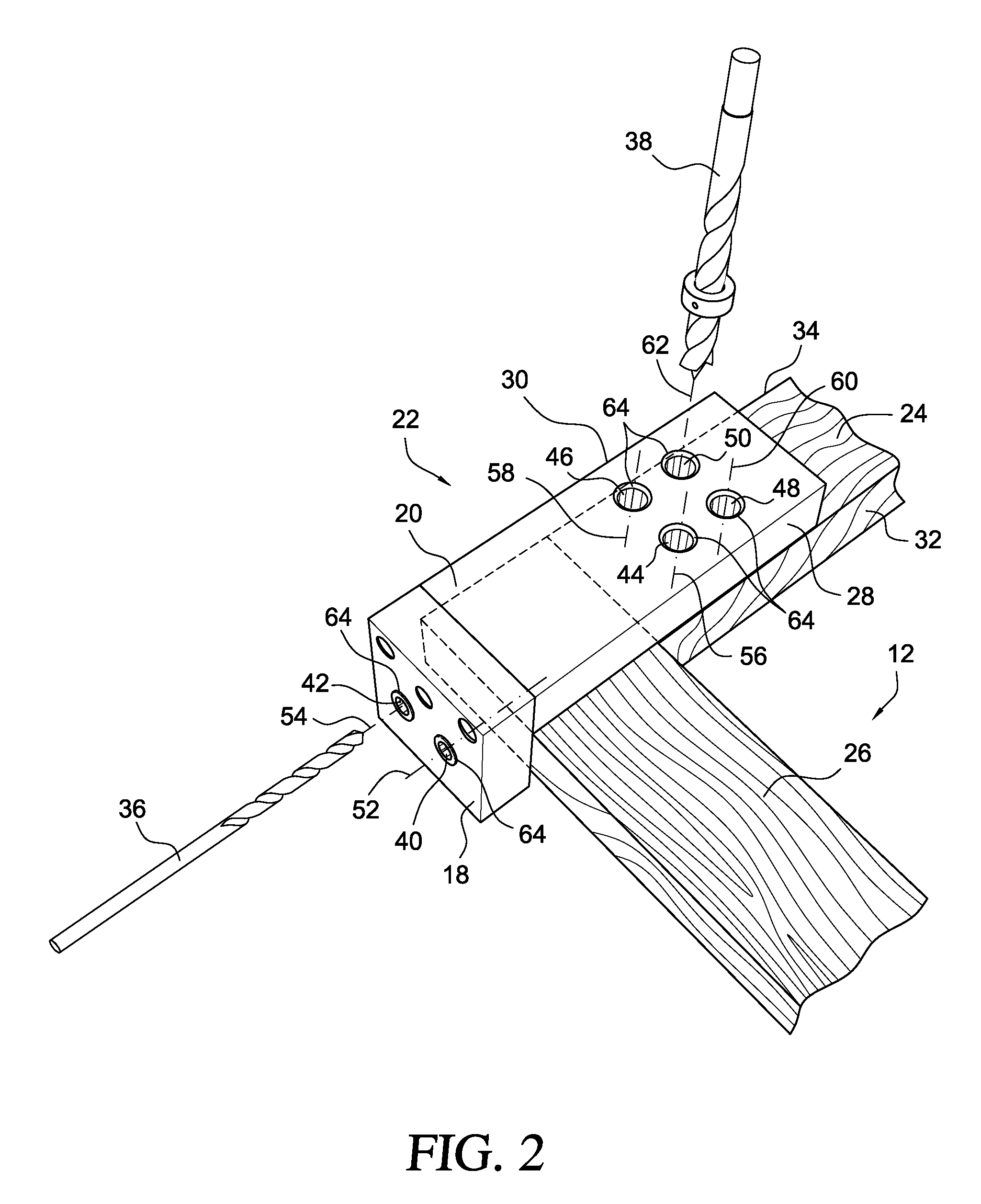
[0028]Referring to the Figures, FIGS. 1-4 show an embodiment of the present invention showing a jig 10 which provides a template for drilling intersecting holes in a work piece 12. A bolt 14 and a barrel-nut 16 are then inserted into each set of intersecting holes to fasten two portions 18, 20 of the work piece 12 together. The jig 10 includes a body 22 having two template portions 18, 20, wherein the two template portions 18, 20 are arranged in an L-shaped configuration. The body 22 is preferably constructed of hard plastic, aluminum or injection molded plastic. In an embodiment of the invention, the body 22 can include two separate, but contiguous template portions 18, 20. Alternatively, the template portions 18, 20 can be an integral part of the body 22.
[0029]In an embodiment of the invention, the jig 10 is sized to have a width corresponding to a typical width of a rail 24 and stile 26 in frame-and-panel construction cabinetry. That is, cabinetry stock is typically three-quarter...
PUM
| Property | Measurement | Unit |
|---|---|---|
| Length | aaaaa | aaaaa |
| Thickness | aaaaa | aaaaa |
| Diameter | aaaaa | aaaaa |
Abstract
Description
Claims
Application Information