Synchronized luminated safety apparel

a safety apparel and synchronized technology, applied in the direction of optical signals, transportation and packaging, cycle equipment, etc., can solve the problems of distracting users from operating, difficult for others to determine signaling intentions, and difficulty in seeing running, turning and braking indicators

Inactive Publication Date: 2010-10-07
GIBSON DELVONO
View PDF33 Cites 86 Cited by
  • Summary
  • Abstract
  • Description
  • Claims
  • Application Information

AI Technical Summary

Benefits of technology

The present invention aims to provide an illuminated safety system that overcomes the shortcomings of previous designs.

Problems solved by technology

The technical problem addressed in this patent is to provide a lighted signaling system for vehicles, including motorcycles, that is connected to the vehicle's electrical indicating system and can be powered by the vehicle's battery. This system enhances the visibility of the vehicle's indicators and makes them easier for other motorists to see and avoid collisions. The invention also includes various methods for activating the lighted signals, such as using a control panel or devices on the vehicle to create a safer and more visible signaling system.

Method used


Image

  • Synchronized luminated safety apparel
  • Synchronized luminated safety apparel
  • Synchronized luminated safety apparel

Examples


Embodiment Construction

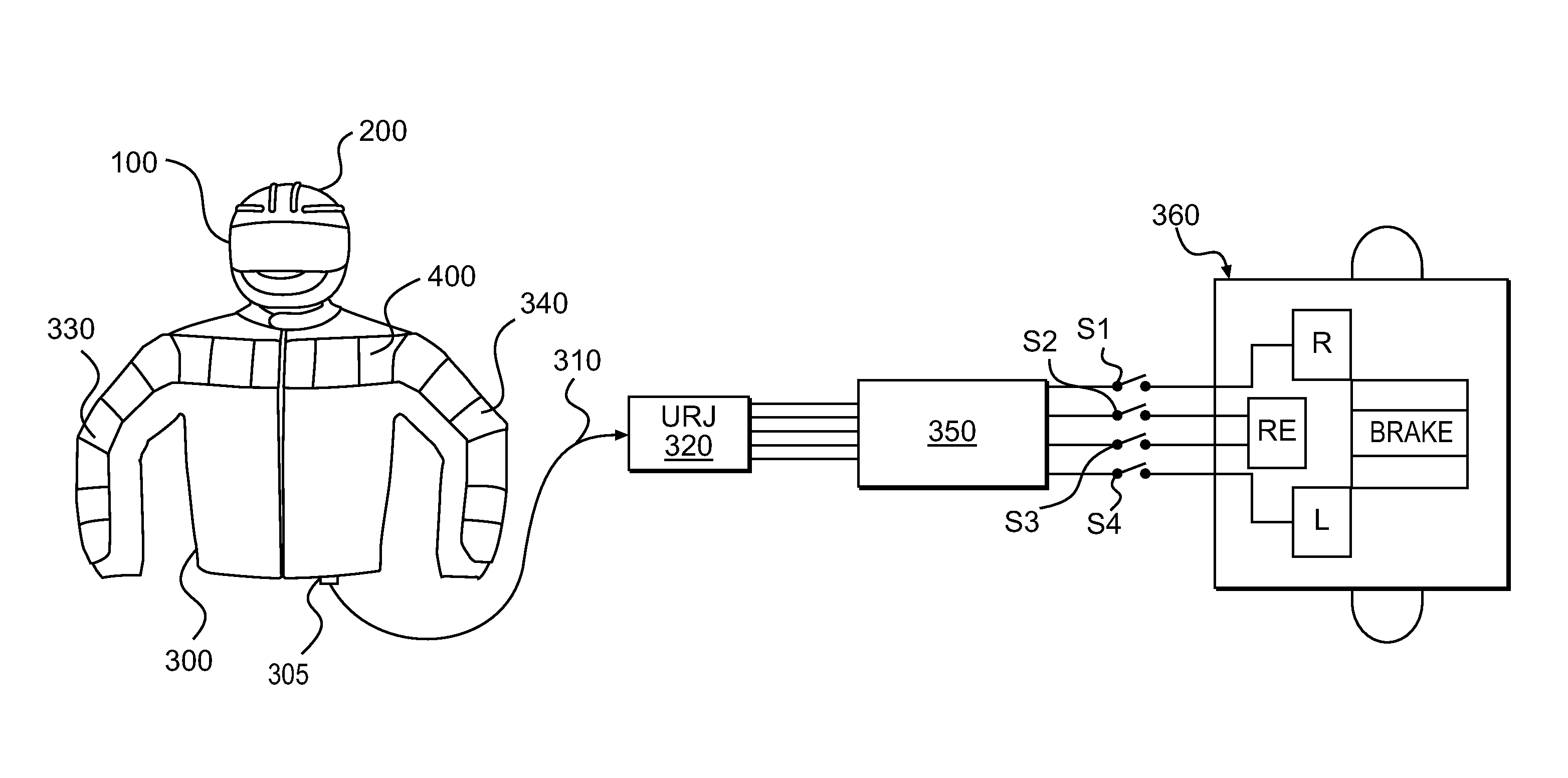
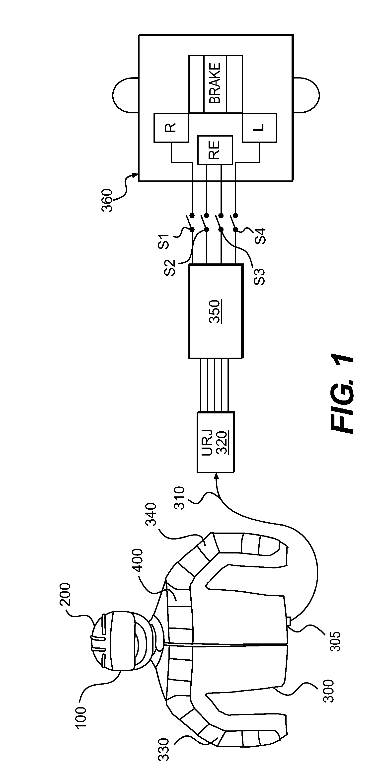
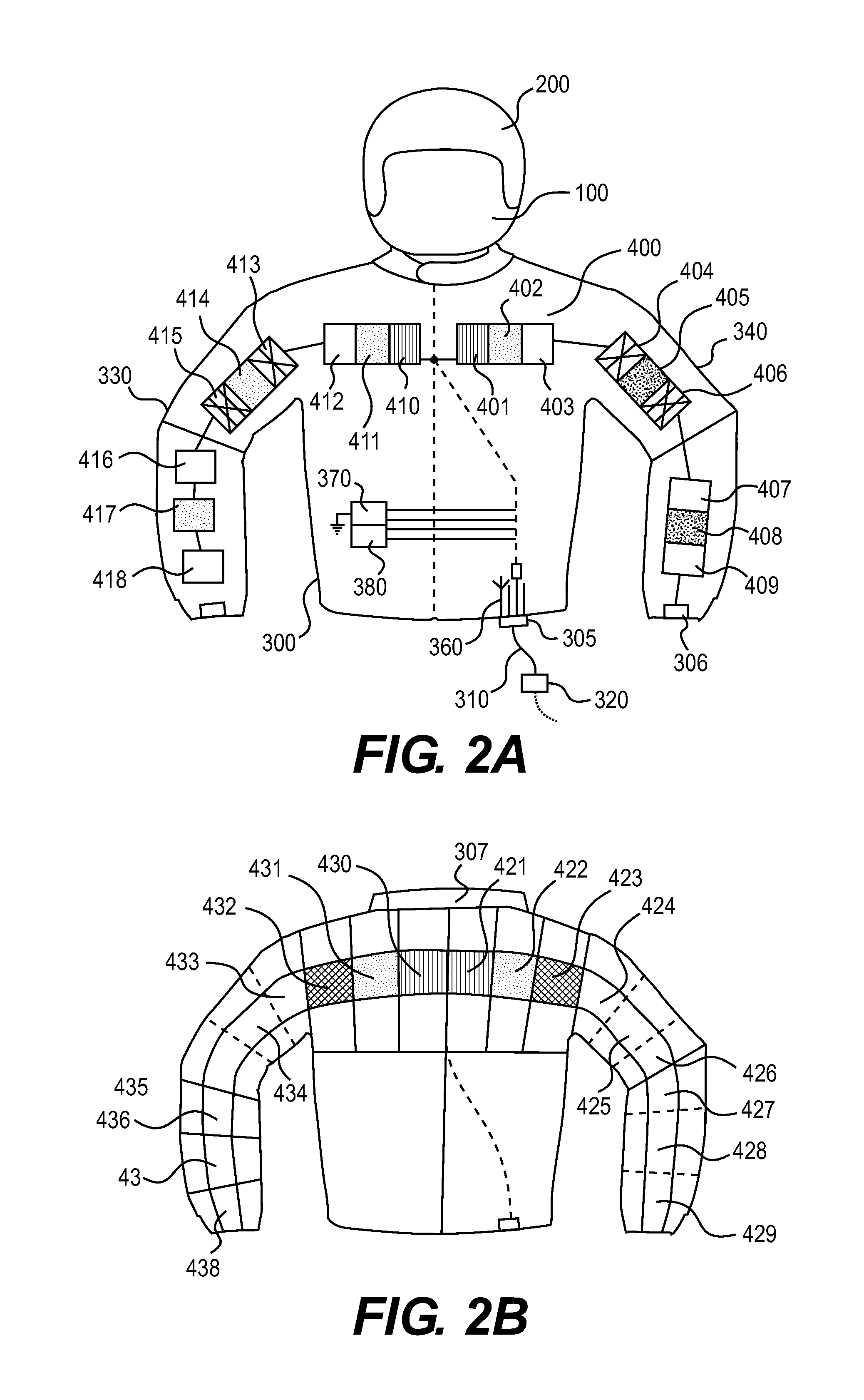
[0082]Referring to FIGS. 1, 2A-2B and 3, a synchronized lighted strip signaling system is provided for a wearer 100. The system includes a synchronized illuminated safety system 400. The wearing apparel comprises a jacket 300, a helmet 200 and a pair of gloves. The system 400 is attachable to the jacket 300. A power source activates the safety synchronized illuminated system 400. When the system 400 is activated by the power source, the jacket 300 worn on the person 100 is more visible to others especially at night. The system 400 comprises an article of apparel (e.g. vest or jacket 300), one or more signaling light strip(s) 401-418 are connected to the front of said jacket 300, a plurality of light strips 421-438 mounted on the rear of the jacket 300. Light strips' system 400 are arranged in one or more signaling pattern(s) block shaped or the smaller segmented stripes as shown in the FIGS. 2A-2B. Connectors 390 and 320 for connecting said helmet 200 and jacket 300 to the electrica...


PUM


Abstract

A safety synchronized illuminated system includes wearing apparels worn on a person. A plurality of light strips is secured to the wearing apparels. The wearing apparels include jacket, helmet and a pair of gloves. A power source, CPU chip for timing, sequencer for time sequential selection and turn signal box activates the plurality of light strips in four items: jacket, helmet, a pair of boots and a pair of gloves in a one-by-one time sequential manner, and synchronized rolling fashion in light patterns and following the traffic color codes via wire or wireless link. Each of items of the apparel can be also activated individually, independently and separately. When the light strips are activated by switch and a power source, the wearing apparels worn on the person is more visible to others especially at night.

Description


Claims


Application Information

Patent Timeline
Owner GIBSON DELVONO
Why Eureka
Try Eureka