Cutting Tool Assembly and Tool Holder Therefor

a technology of cutting tool and tool head, which is applied in the direction of shaping cutter, wood boring tool, manufacturing tool, etc., can solve the problems of relative cost of solid carbide tooling, general perpendicular direction of workpiece, and inability to accurately position the tool head of the cutting apparatus

Active Publication Date: 2010-10-07
ISCAR LTD
View PDF12 Cites 36 Cited by
  • Summary
  • Abstract
  • Description
  • Claims
  • Application Information

AI Technical Summary

Problems solved by technology

This cutting tool assembly attempts to provide a swift and accurate means for re-orienting the tool head following removal from the tool holder, although it is suggested that there may be difficulties initially locating the slide member within the dovetail groove.
A disadvantage of the first embodiment of this cutting tool assembly is that a major cutting force component tangential to a rotating workpiece is directed generally perpendicular to and away from the tool holder seat surface.
This cutting tool employs a relatively large solid carbide cutting insert providing both a means of attachment to the tool holder and a single cutting end portion, which is disadvantageous when considering the relative expense of solid carbide tooling.
This invention has a disadvantage in that the cutting apparatus provides only moderate precision of tool head positioning relative to the mount in a vertical direction.
Another disadvantage is the possibility that the tool head may easily separate and fall from the mount when the head screw is removed.

Method used


Image

  • Cutting Tool Assembly and Tool Holder Therefor
  • Cutting Tool Assembly and Tool Holder Therefor
  • Cutting Tool Assembly and Tool Holder Therefor

Examples


second embodiment

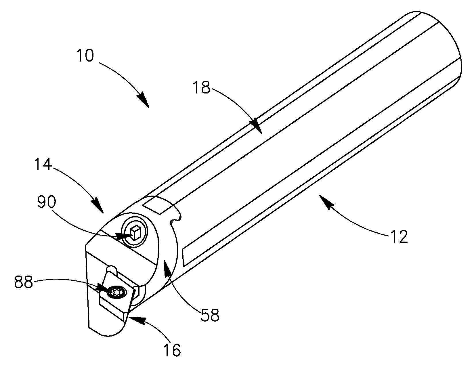
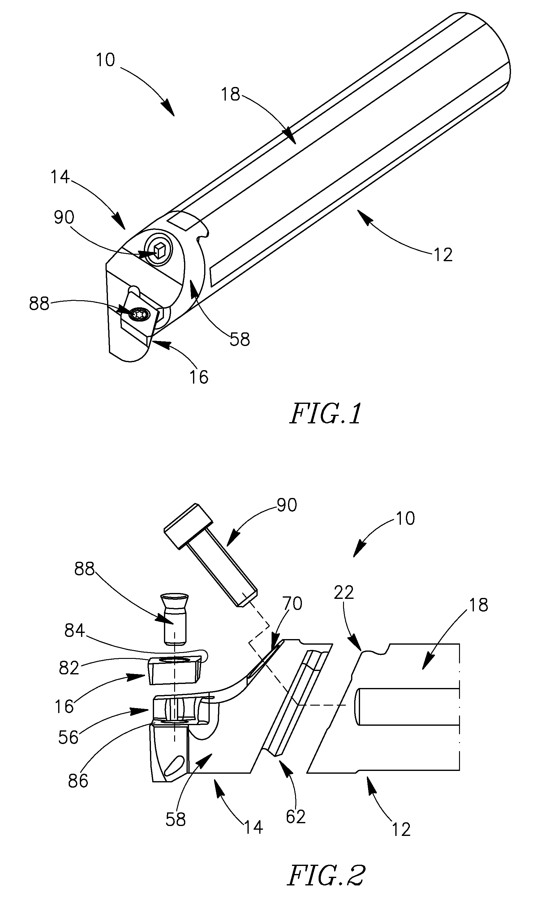
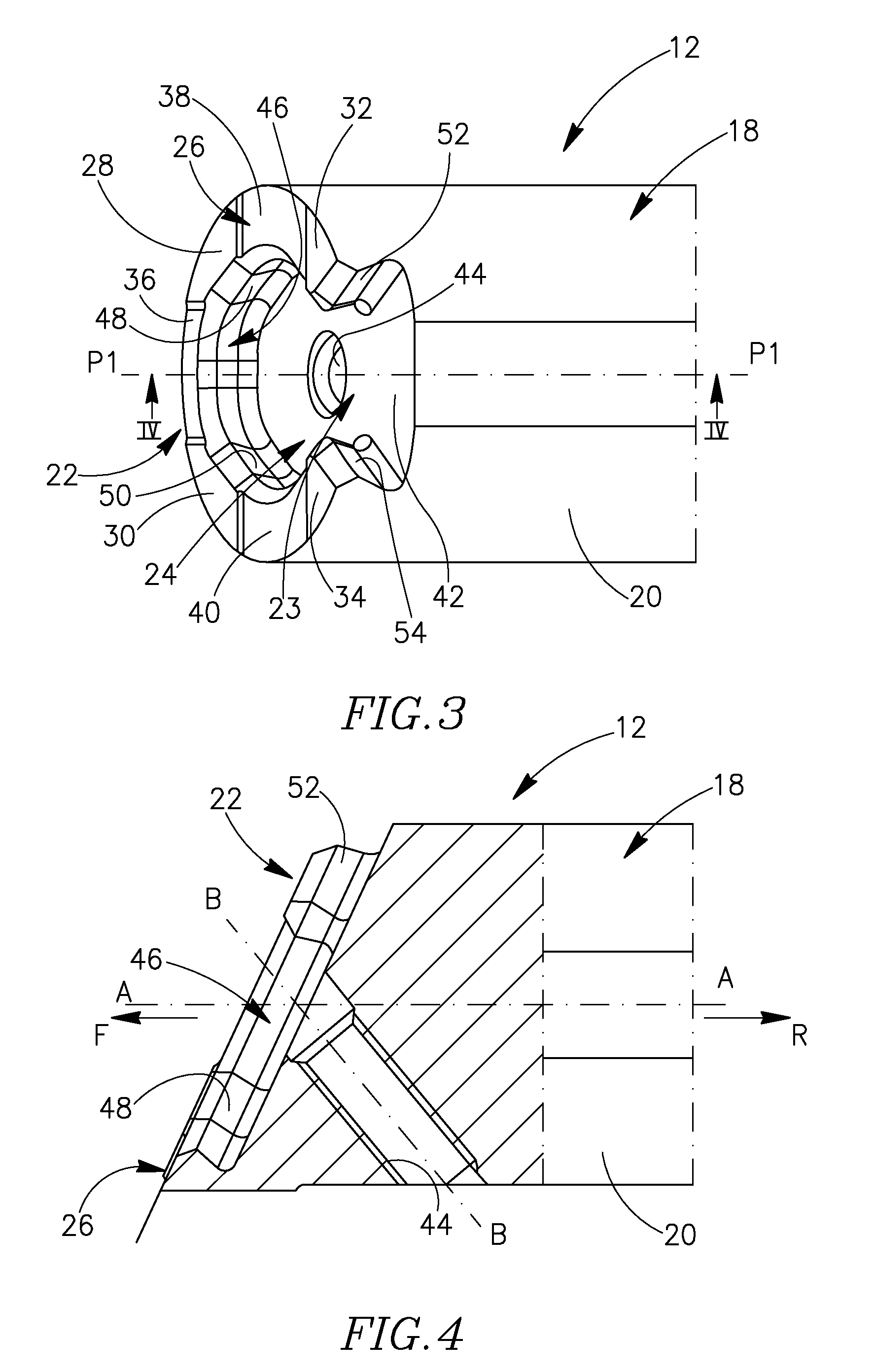
[0053]the present invention will now be described referring to FIGS. 12 to 15, showing a cutting tool assembly 110 comprising a tool holder 112 having a front mating end 122 and a tool head 114 having a rear mating end 162.

first embodiment

[0054]Some elements of the cutting tool assembly 110 are common to those of the first embodiment and are shown in FIGS. 1 to 11, and therefore description of these elements will be omitted for simplicity.

[0055]It should also be understood that some elements from the rear mating end 62 of the tool head 14 in the first embodiment will now be associated with the front mating end 122 of the tool holder 112 in the second embodiment, and some elements from the front mating end 22 of the tool holder 12 in the first embodiment will now be associated with the rear mating end 162 of the tool head 114 in the second embodiment.

[0056]The front mating end 122 of the tool holder 112 includes a male type tool head coupler 123 in the form of an engagement protrusion 124 partially bordered by a lower planar supporting surface 126, and the rear mating end 162 of the tool head 114 includes a female type tool holder coupler 163 in the form of a tool holder receiving pocket 164 partially bordered by a ra...


PUM

PropertyMeasurementUnit
angleaaaaaaaaaa
cutting forceaaaaaaaaaa
clamping forceaaaaaaaaaa

Abstract

A cutting tool assembly for boring and internal grooving operations includes a tool head having a removably secured cutting insert at a forward insert receiving end and a rear mating end with a male or female type tool holder coupler in the form of an engagement protrusion or cutting holder receiving pocket. The tool head is fixed to a tool holder with a front mating end having a female or male tool head coupler in the form of a tool head receiving pocket or engagement protrusion. Following assembly, at least three abutting wall surfaces and an adjacent support surface of the tool holder coupler are in contact with at least three non-coplanar abutment surfaces and an adjacent supporting surface of the tool head coupler, respectively, and a fastening screw member extends through a through bore in the tool holder coupler engaging a threaded screw bore in the tool head coupler.

Description

FIELD OF THE INVENTION[0001]The present invention relates to a cutting tool assembly comprising a tool holder and tool head for use in metal cutting processes in general, and for boring and internal grooving operations in particular.BACKGROUND OF THE INVENTION[0002]Within the field of internal grooving and boring of a rotating metal workpiece, cutting inserts manufactured from a hard material, namely cemented carbide, may be secured to a tool holder in many different ways.[0003]U.S. Pat. No. 3,289,273 discloses a cutting tool assembly comprising a tool holder with a longitudinal axis and a removable tool head having a solid carbide cutting insert brazed onto the tool head. The tool holder includes a seat with a dovetailed groove having two side surfaces inclined at an acute angle to the seat surface, and the tool head includes a seating surface with a dovetailed slide member having two complementary side surfaces, where each of these surfaces is accurately machined so that the tool ...

Claims


Application Information

Patent Timeline
Patent Type & Authority Applications(United States)
IPC IPC(8): B23B29/02B23B29/12
CPCB23B27/007B23B29/046B23B2220/123Y10T407/227Y10T408/95Y10T408/907Y10T82/2585Y10T407/2272B23B27/00B23B27/16B23B29/04B23Q3/00
Inventor HECHT
Owner ISCAR LTD
Why Eureka
Try Eureka