
Firing patterns for deep brain transcranial magnetic stimulation

a transcranial magnetic stimulation and firing pattern technology, applied in magnetotherapy, magnetotherapy using coils/electromagnets, magnetotherapy, etc., can solve problems such as adverse effects

Active Publication Date: 2010-10-07
BRAINSWAY
View PDF101 Cites 59 Cited by
  • Summary
  • Abstract
  • Description
  • Claims
  • Application Information

AI Technical Summary

Benefits of technology

[0013]This approach may also be used to take advantage of the individual properties of different brain regions, permitting each region to be stimulated with the pulse sequence that maximally contributes to the overall intended effect of the treatment. For example, adverse effects may result if pulse rates exceed 3 Hz when the pulse trajectory passes through the right dorsolateral prefrontal cortex on the way to a cingulate target. Consequently, it may benefit the overall treatment strategy to limit the rate of pulses passing through the right dorsolateral prefrontal cortex, even though a faster pulse rate would help the temporal summation effect.

Problems solved by technology

For example, adverse effects may result if pulse rates exceed 3 Hz when the pulse trajectory passes through the right dorsolateral prefrontal cortex on the way to a cingulate target.

Method used


Image

  • Firing patterns for deep brain transcranial magnetic stimulation
  • Firing patterns for deep brain transcranial magnetic stimulation
  • Firing patterns for deep brain transcranial magnetic stimulation

Examples


Embodiment Construction

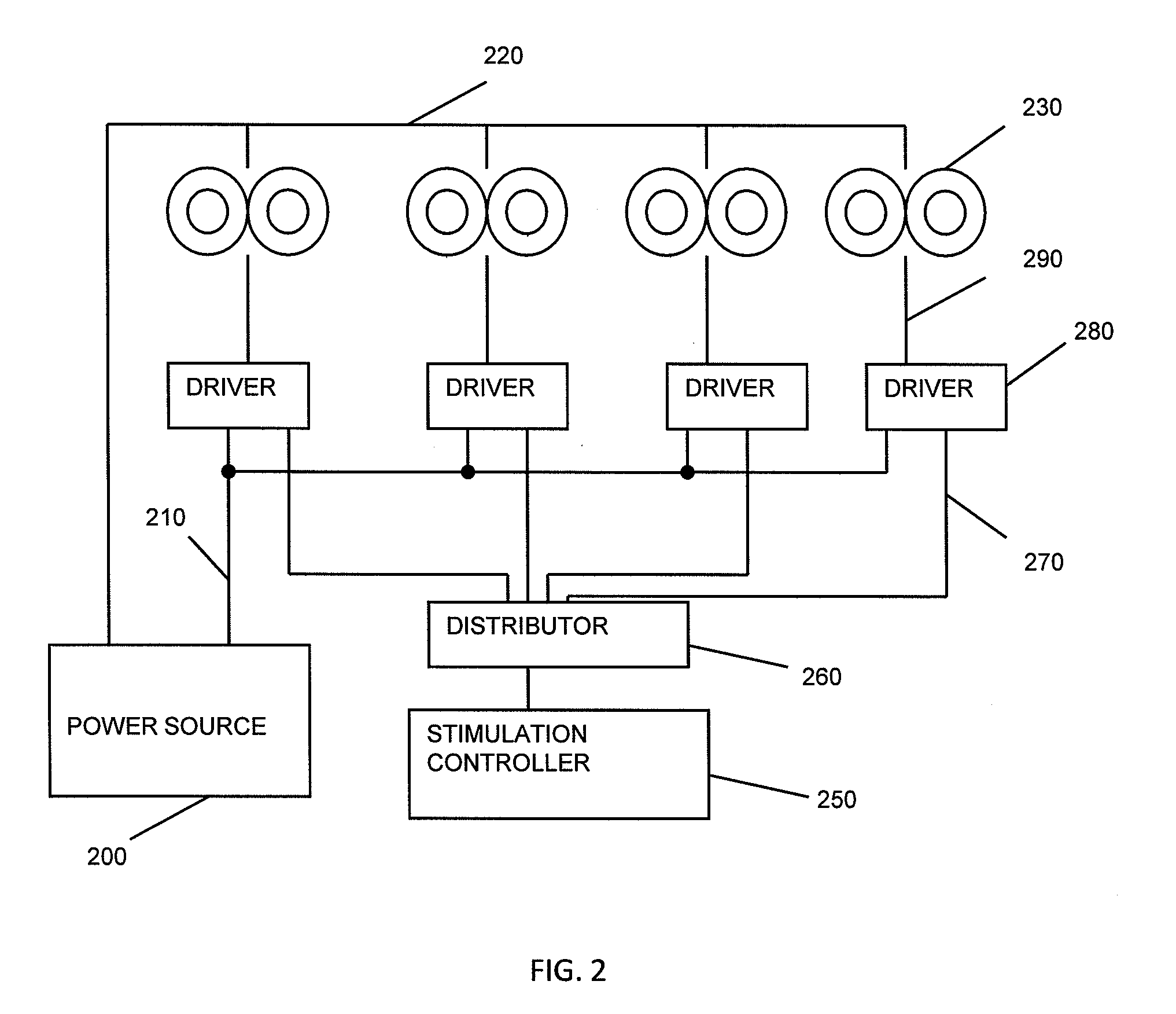
[0028]The Transcranial Magnetic Stimulation (TMS) methods, devices and systems described herein are capable of triggering action potential (including specified patterns of action potentials) in one or more target brain regions without trigger action potential sin nearby non-target regions, including regions that are superficial (e.g., between the target region and the external magnets(s) stimulating the brain). These TMS systems may support a variety of action potential firing patterns by controlling the pulsing of multiple, independently triggerable, electromagnets from one or more energy sources. The system may also monitor or control the one or more power supplies so that there is sufficient capacity from the power supplies so when a given pulse is triggered, adequate power is available to deliver a stimulus from each electromagnet as needed to trigger the desired action potentials from the target brain region.

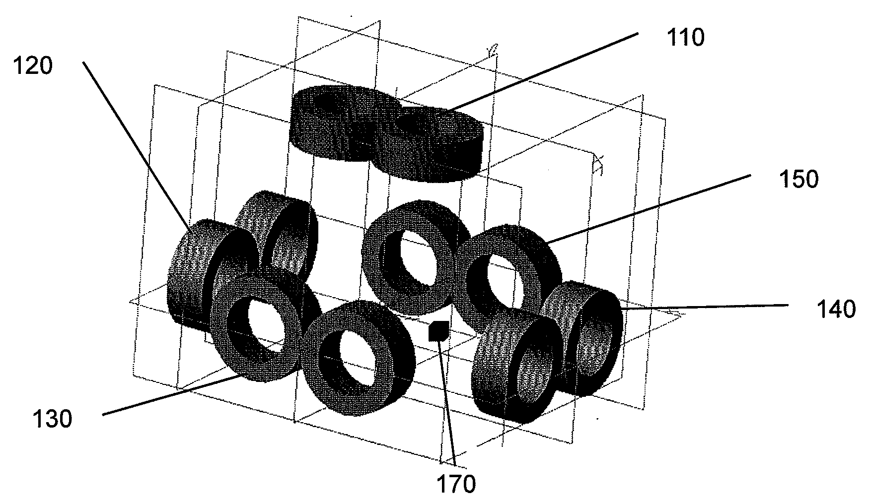
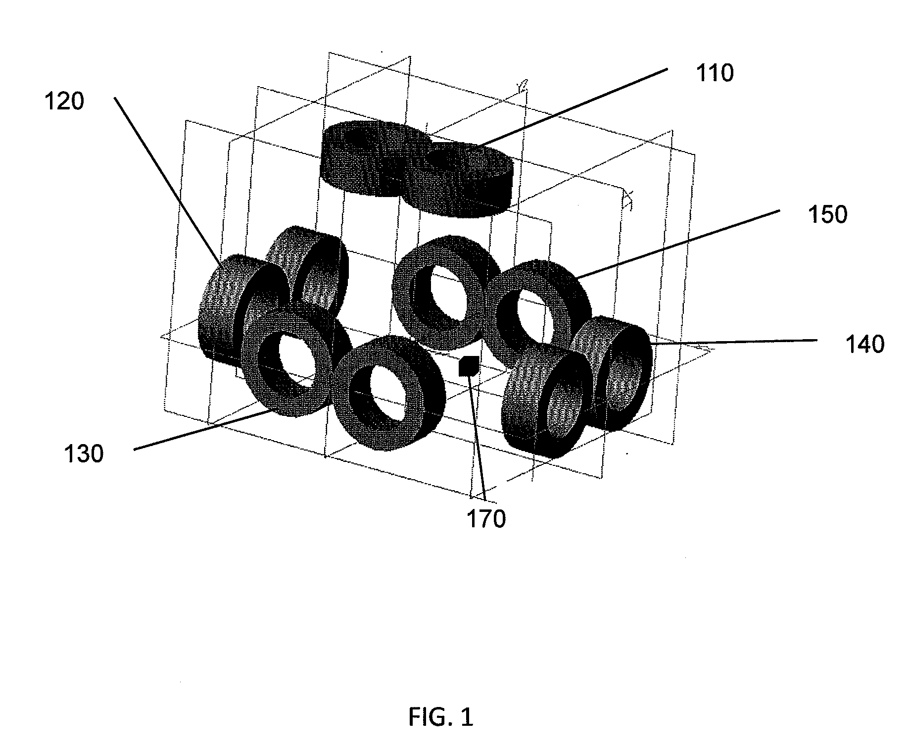
[0029]FIG. 1 illustrates a configuration incorporating five electromag...


PUM


Abstract

Methods, devices and systems for Transcranial Magnetic Stimulation (TMS) are provided for synchronous, asynchronous, or independent triggering the firing multiple of electromagnets from either a single power source or multiple energy sources. These methods are particularly useful for stimulation of deep (e.g., sub-cortical) brain regions, or for stimulation of multiple brain regions, since controlled magnetic pulses reaching the deep target location may combine to form a patterned pulse train that activates the desired volume of target tissue. Furthermore, the methods, devices and systems described herein may be used to control the rate of firing of action potentials in one or more brain regions, such as slow or fast rate rTMS. For example, described herein are multiple electromagnetic stimulation sources, each of which are activated independently to create a cumulative effect at the intersections of the electromagnetic stimulation trajectories, typically by means of a computerized calculation.

Description

CROSS REFERENCE TO RELATED APPLICATIONS[0001]This application claims priority to the following applications: U.S. Provisional Patent Application Ser. No. 60 / 956,920, filed on Aug. 20, 2007, titled “FIRING PATTERNS FOR DEEP BRAIN TRANSCRANIAL MAGNETIC STIMULATION.”; U.S. Provisional Patent Application Ser. No. 60 / 970,958, filed on Sep. 9, 2007, titled “PULSING MULTIPLE INDEPENDENTLY TRIGGERED ELECTROMAGNETS FROM ONE OR MORE ENERGY SOURCES.”; and U.S. Provisional Patent Application Ser. No. 61 / 077,488, filed on Jul. 2, 2008, titled “DIFFERENTIAL PULSE PATTERNS IN PARALLEL STIMULATION ARRAYS.” Each of these applications is herein incorporated by reference in its entirety.INCORPORATION BY REFERENCE[0002]All publications and patent applications mentioned in this specification are herein incorporated by reference in their entirety to the same extent as if each individual publication or patent application was specifically and individually indicated to be incorporated by reference.FIELD OF ...

Claims


Application Information

Patent Timeline
IPC IPC(8): A61N2/02
CPCA61N2/006A61N2/02
Inventor MISHELEVICH, DAVID J.SCHNEIDER, M. BRET
Owner BRAINSWAY
Learn More