
Gantry and switches for position-based triggering of tms pulses in moving coils

a position-based triggering and moving coil technology, applied in magnetotherapy, magnetotherapy using coils/electromagnets, magnetotherapy, etc., can solve the problems of high adverse effects, slow and expensive use of robotics and computerized motion control, and low therapeutic effect of approaches

Inactive Publication Date: 2010-10-07
CERVEL NEUROTECH
View PDF81 Cites 37 Cited by
  • Summary
  • Abstract
  • Description
  • Claims
  • Application Information

AI Technical Summary

Problems solved by technology

While it is possible to simply deliver a constant stream of pulses throughout a stereotyped movement of the coil(s), such an approach is likely to fall short on therapeutic effects and measure high on adverse effects.
A disadvantage of this approach is that pulses will likely be also delivered at inappropriate locations, producing unwanted side effects.
Using robotics and computerized motion control is both slow and expensive.

Method used


Image

  • Gantry and switches for position-based triggering of tms pulses in moving coils
  • Gantry and switches for position-based triggering of tms pulses in moving coils
  • Gantry and switches for position-based triggering of tms pulses in moving coils

Examples


Embodiment Construction

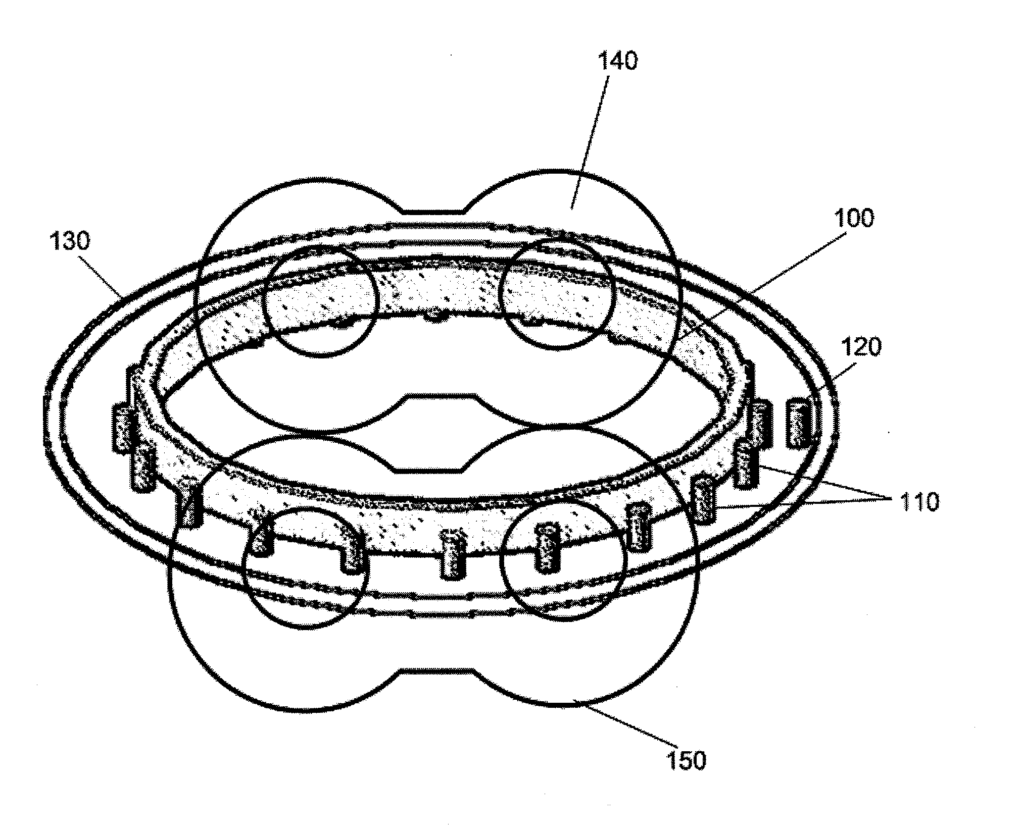
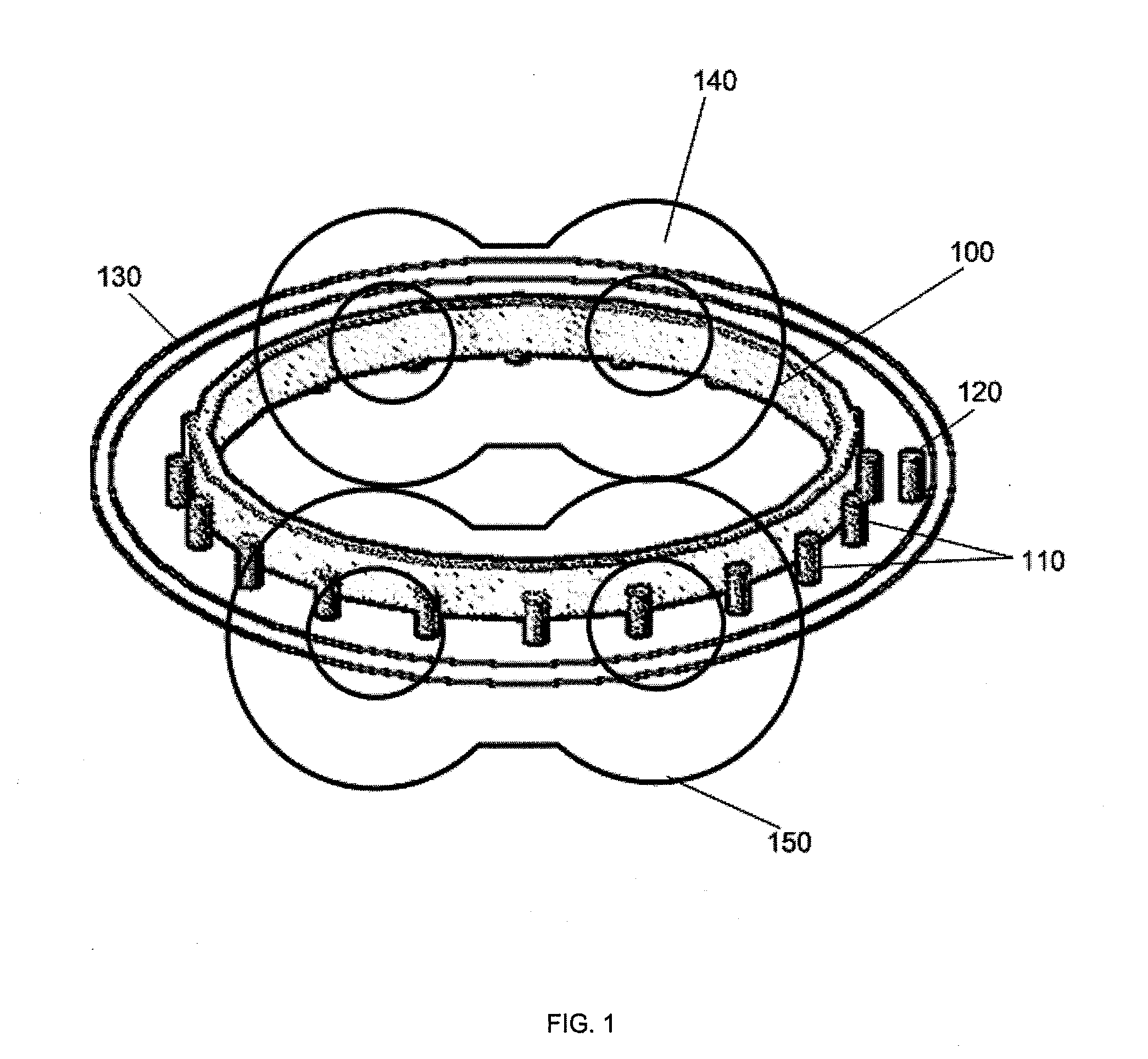
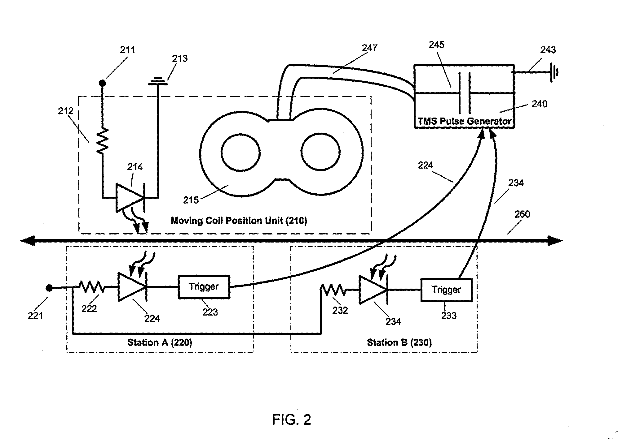
[0014]FIG. 1 illustrates an embodiment involving a circular frame gantry 100. Positioned around the perimeter of frame 100 are trigger points 110. These trigger points need not be uniformly distributed around the frame perimeter. Embodiments of trigger the devices 120 to be triggered when trigger points 110 are in proximity as shown in FIG. 1 may include an electromechanical switch (such as a standard normally-open push-button switch (Jameco Electronics, Belmont, Calif.)) or switches held on a support 130 tripped by physical or non-physical contact with trigger points. Alternative embodiments for the switches may include Hall effect sensors, reed switches, interruption of light beams, interruption of audio beams, microphones where the trigger points emit audio, or radio-frequency devices such as RFID tags, or similar devices. For locations that should not be stimulated (when it is desired to protect underlying tissue), the trigger is not installed or otherwise not enabled such that ...


PUM


Abstract

When a mechanical frame or gantry is used to move one or more electromagnets about a subject, the pulsed magnetic fields of the magnets need to be triggered, but only when the coil is in an appropriate physical position. Trigger points are established along the movement pathway (e.g., along the support frame) for the electromagnets that trigger the pulsation of the current being supplied to the given electromagnet. Use of the present invention allows firing of a magnetic coil to coordinate with the position of that coil, without need for expensive robotics or computerized motion control.

Description

CROSS REFERENCE TO RELATED APPLICATIONS[0001]This application claims priority to U.S. Provisional Patent Application Ser. No. 60 / 954,018, filed on Aug. 13, 2007, titled “GANTRY AND SWITCHES FOR POSITION-BASED TRIGGERING OF TMS PULSES IN MOVING COILS.”INCORPORATION BY REFERENCE[0002]All publications and patent applications mentioned in this specification are herein incorporated by reference in their entirety to the same extent as if each individual publication or patent application was specifically and individually indicated incorporated by reference.FIELD OF THE INVENTION[0003]The devices and methods described herein relate generally to the triggering of electromagnets used for Transcranial Magnetic Stimulation.BACKGROUND OF THE INVENTION[0004]Magnetic stimulation of the body, for example repetitive transcranial magnetic stimulation (rTMS), is most efficiently accomplished if magnetic pulses are discharged from the coil while the coil is in the proper position. While it is possible ...

Claims


Application Information

Patent Timeline
Patent Type & Authority Applications(United States)
IPC IPC(8): A61N2/02
CPCA61N2/02A61N2/006
Inventor SCHNEIDER, M. BRETMISHELEVICH, DAVID J.
Owner CERVEL NEUROTECH
Learn More