Heat sinks with distributed and integrated jet cooling

a technology of integrated cooling and heat sinks, applied in the direction of lighting and heating apparatus, electrical apparatus construction details, semiconductor/solid-state device details, etc., can solve the problems of limited heat removal capability, limited amount of available space for thermal management systems, and formidable challenges in thermal management systems designed to provide cooling for embedded electronics

Inactive Publication Date: 2010-10-14
GENERAL ELECTRIC CO
View PDF19 Cites 33 Cited by
  • Summary
  • Abstract
  • Description
  • Claims
  • Application Information

AI Technical Summary

Problems solved by technology

Environments having embedded electronic systems, hereinafter embedded environments or heated environments, offer challenges for thermal management.
The design of thermal management systems to provide cooling for embedded electronics is a formidable challenge due to space limitations.
Examples of embedded electronic systems include single board computers, programmable logic controllers (PLCs), operator interface computers, laptop computers, cell phones, personal digital assistants (PDAs), personal pocket computers, and other small electronic devices, there is a limited amount of available space for thermal management systems.
However, such techniques have limited heat removal capabilities.

Method used


Image

  • Heat sinks with distributed and integrated jet cooling
  • Heat sinks with distributed and integrated jet cooling
  • Heat sinks with distributed and integrated jet cooling

Examples


Embodiment Construction

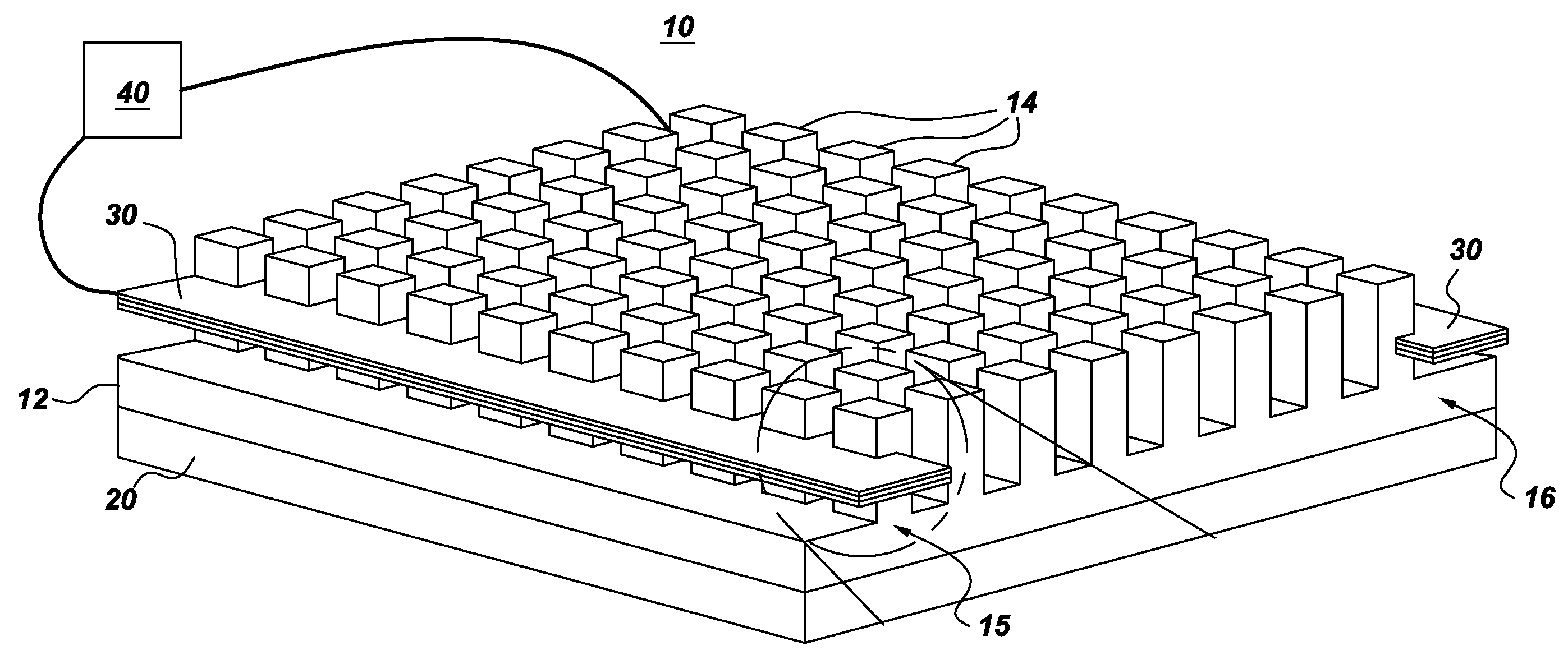
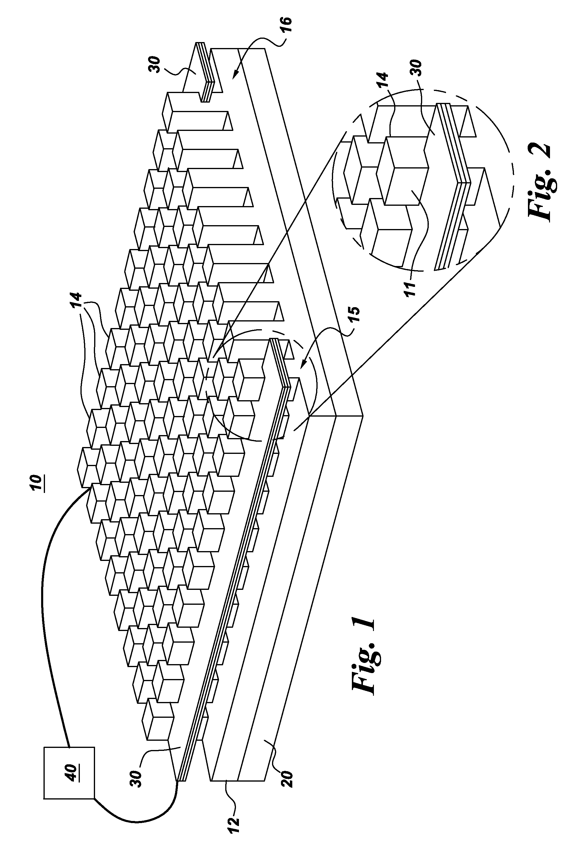
[0025]FIGS. 1 and 2 illustrate a heat sink 10 with distributed jet cooling. As shown, for example, in FIG. 1, the heat sink comprises a base 12 for thermal connection to at least one heated object 20. The heated object 20 may be any object requiring cooling, non-limiting examples of which include high power processors and power electronics. The base 12 (base plate or sink plate) can be formed of a variety of thermally conductive materials, as known in the art. The heat sink 10 further includes an array of fins 14 thermally coupled to the base. The fins may be arranged in a two-dimensional array of “pin fins” as shown, for example in FIG. 1. For other arrangements, the fins 14 may take the form of a one-dimensional array of “plate fins” defining slots between them, as shown for example in FIGS. 7 and 8. Briefly, the heat from the heated object 20 is transferred into the base 12, which in turn transfers heat into the fins 14. The fins 14 increase the surface area for heat transfer for...


PUM


Abstract

A heat sink with distributed jet cooling is provided. The heat sink includes a base for thermal connection to at least one heated object, an array of fins thermally coupled to the base, and at least one multi-orifice synthetic jet or multiple single orifice jets disposed on a side of the array of fins. A heat sink with distributed and integrated jet cooling is also provided and includes a base and an array of fins. Respective ones of at least a subset of the fins comprise a synthetic jet configured to eject an ambient fluid into an ambient environment of the fins and base. Another heat sink with distributed and integrated jet cooling is provided and includes a base, an array of fins and multiple synthetic jets coupled to respective ones of the fins. The synthetic jets are provided for at least a subset of the fins.

Description

BACKGROUND[0001]The invention relates generally to thermal management systems, and more particularly to thermal management systems for use in embedded environments.[0002]Environments having embedded electronic systems, hereinafter embedded environments or heated environments, offer challenges for thermal management. Such systems produce waste heat as a part of their normal operation, heat that must be removed for proper performance and reliability of the embedded electronics. The design of thermal management systems to provide cooling for embedded electronics is a formidable challenge due to space limitations. Examples of embedded electronic systems include single board computers, programmable logic controllers (PLCs), operator interface computers, laptop computers, cell phones, personal digital assistants (PDAs), personal pocket computers, and other small electronic devices, there is a limited amount of available space for thermal management systems. It has been known to use passiv...

Claims


Application Information

Patent Timeline
Patent Type & Authority Applications(United States)
IPC IPC(8): F28F13/00
CPCH01L23/467H01L2924/0002H01L2924/00
Inventor ARIK, MEHMETICOZ, TUNCRIVAS DAVILA, JUAN MANUELSEELEY, CHARLES ERKLINUTTURKAR, YOGEN VISHWASWEAVER, JR., STANTON EARL
Owner GENERAL ELECTRIC CO
Why Eureka
Try Eureka