Transponder detector for an RFID system generating a progression of detection signals

a transponder detector and detection signal technology, applied in the field of rfid systems, can solve the problems of reducing the detection signal output rate, and reducing so as to increase the capacitance and resistance. , the effect of decreasing the capacitance and resistan

Active Publication Date: 2010-10-14
ASSA ABLOY AB
View PDF32 Cites 17 Cited by
  • Summary
  • Abstract
  • Description
  • Claims
  • Application Information

AI Technical Summary

Problems solved by technology

Although a reader can continuously operate in the data transaction mode, the functions of the data transaction mode typically have a relatively high power demand, which can rapidly deplete the power supply of the reader.
This condition is particularly undesirable when the reader is powered by a self-contained portable power supply, such as a small disposable or rechargeable battery, which has a finite life.
In particular, inductive coupling of the reader antenna to the nearby transponder antenna causes a change in the response on the reader antenna.

Method used


Image

  • Transponder detector for an RFID system generating a progression of detection signals
  • Transponder detector for an RFID system generating a progression of detection signals
  • Transponder detector for an RFID system generating a progression of detection signals

Examples


Embodiment Construction

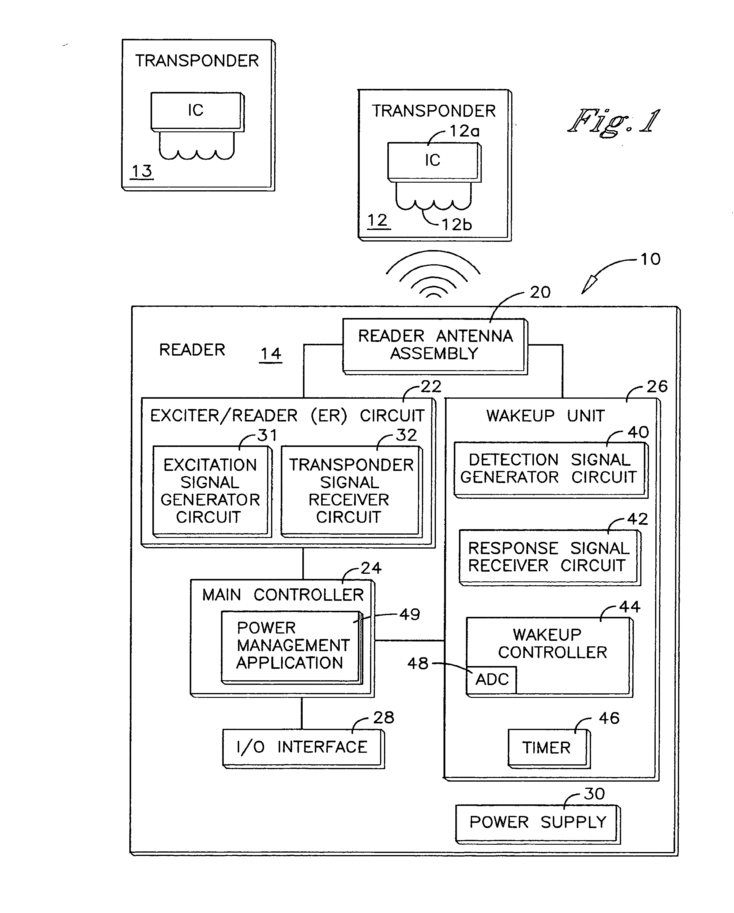
[0037]An RFID system is shown in FIG. 1 and generally designated 10. The RFID system 10 comprises a transponder 12 and a reader 14. The reader 14 includes a transponder detector of the present invention which is described below. The transponder 12 is preferably a passive transponder which does not require an internal power supply. Instead the electrical power required to operate the transponder 12 is supplied to the transponder 12 by electromagnetic energy transmitted from the reader 14. Accordingly, the transponder 12 is operational when it receives electromagnetic waves from the reader, which are of a specific frequency and of a sufficient strength to power up the transponder.

[0038]The transponder 12 comprises a number of functional elements including a transponder integrated circuit (IC) 12a and a transponder antenna 12b. The transponder IC 12a embodies the processing and memory capabilities of the transponder 12. The transponder antenna 12b is coupled to the transponder IC 12a a...


PUM


Abstract

A transponder detector is provided with capabilities for detecting the presence and type of a transponder in its read range while operating at low power. The transponder detector includes an antenna assembly and a detection signal generator circuit coupled to the antenna assembly. The detection signal generator circuit is capable of generating a progression of detection signals on the antenna assembly across a range of frequencies. The transponder detector further includes a response signal receiver circuit coupled to the antenna assembly to receive a progression of response signals from the antenna assembly resulting from the progression of detection signals. A controller is coupled to the response signal receiver circuit which determines the presence and type of the transponder based on an evaluation of a transponder detection parameter in the progression of response signals.

Description

TECHNICAL FIELD[0001]The present invention relates generally to RFID systems and, more particularly, to the construction and operation of a transponder detector utilized as a stand-alone unit or in association with a reader of an RFID system.BACKGROUND OF THE INVENTION[0002]Radio frequency identification (RFID) systems typically include at least one reader and a plurality of transponders, which are commonly termed credentials, cards, tags, or the like. Each transponder is an active or passive radio frequency communication device which is directly attached to or embedded in an article to be identified or otherwise characterized by the reader. Alternatively, the transponder is embedded in a portable substrate, such as a card, tag, or the like, carried by a person or an article to be identified or otherwise characterized by the reader.[0003]An active transponder is powered up by its own internal power supply, such as an internal battery, which provides the operating power for the trans...

Claims


Application Information

Patent Timeline
Patent Type & Authority Applications(United States)
IPC IPC(8): H04Q5/22G08B23/00H04W4/80
CPCG06K7/0008G06K7/10128H04B5/0068H04W4/008H04B5/0075H04W4/80Y02D30/70
Inventor BORCHERDING, ERIC J.
Owner ASSA ABLOY AB
Why Eureka
Try Eureka