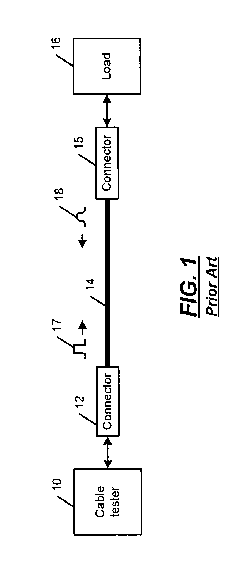
Cable tester

a test system and cable technology, applied in the direction of instruments, data switching networks, line-transmission details, etc., can solve the problems of weak return signals that cannot be analyzed, increase the total cost of ownership, and generate inaccurate results

Active Publication Date: 2011-03-15
MARVELL ASIA PTE LTD
View PDF72 Cites 181 Cited by
  • Summary
  • Abstract
  • Description
  • Claims
  • Application Information

AI Technical Summary

Benefits of technology

[0012]A physical layer module (PHY) of a network device comprises a control module and a cable-test module. The control module selectively generates a cable-test enable signal to test a cable including four pairs of twisted wire. The cable-test module tests the cable based on the cable-test enable signal. The cable-test module transmits test signals on the four pairs at a first time and receives re...

Problems solved by technology

Cabling problems can cause a significant amount of network downtime and can require troubleshooting resources, which increase the total cost of ownership.
Conventional cable tests, however, may generate inaccurate results when the cable 14 is terminated by an active link partner generating link signals during a test.
Weak r...

Method used


Image

  • Cable tester
  • Cable tester
  • Cable tester

Examples


Embodiment Construction

[0071]The following description is merely exemplary in nature and is in no way intended to limit the disclosure, its application, or uses. For purposes of clarity, the same reference numbers will be used in the drawings to identify similar elements. As used herein, the term module, circuit and / or device refers to an Application Specific Integrated Circuit (ASIC), an electronic circuit, a processor (shared, dedicated, or group) and memory that execute one or more software or firmware programs, a combinational logic circuit, and / or other suitable components that provide the described functionality. As used herein, the phrase at least one of A, B, and C should be construed to mean a logical (A or B or C), using a non-exclusive logical or. It should be understood that steps within a method may be executed in different order without altering the principles of the present disclosure.

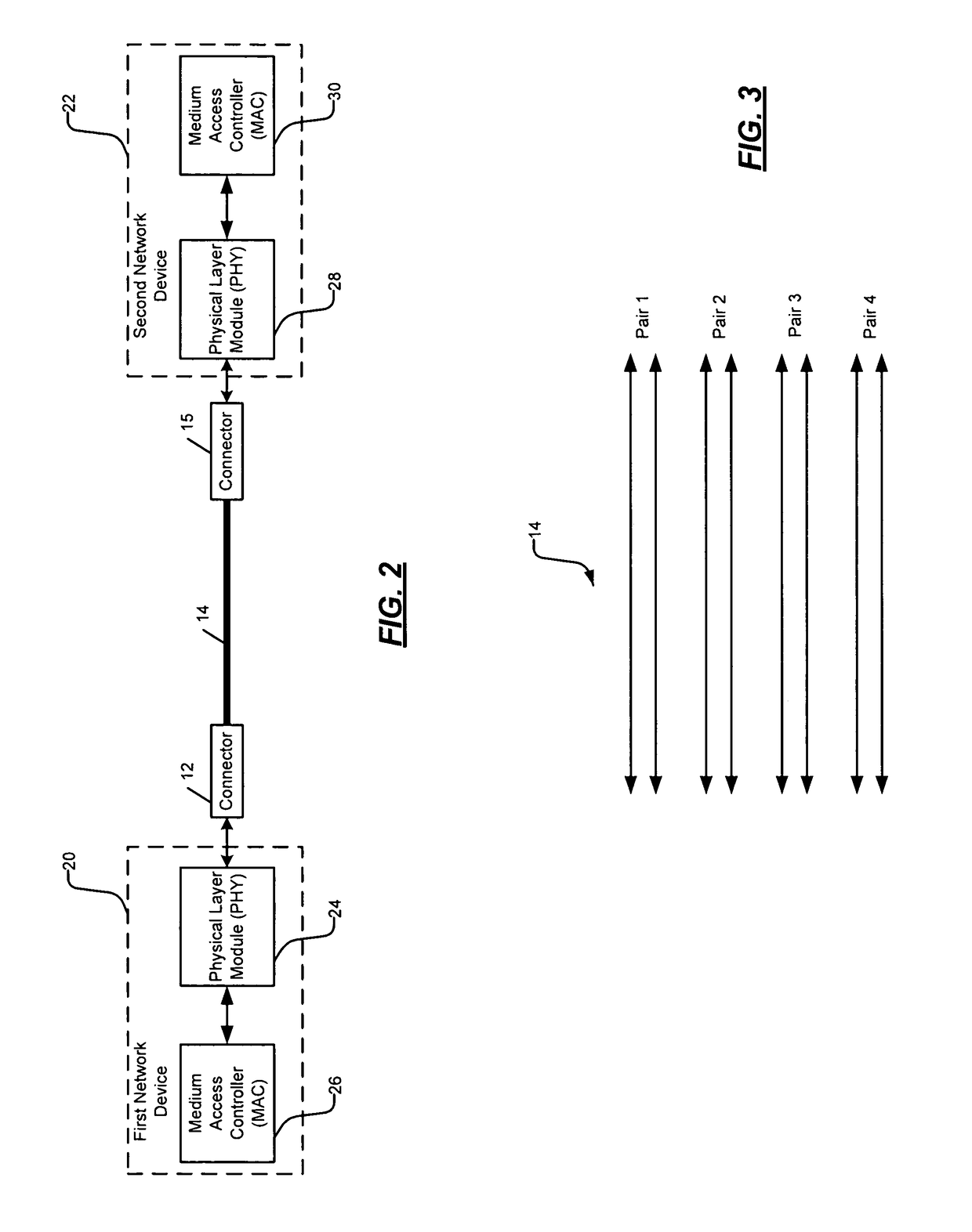
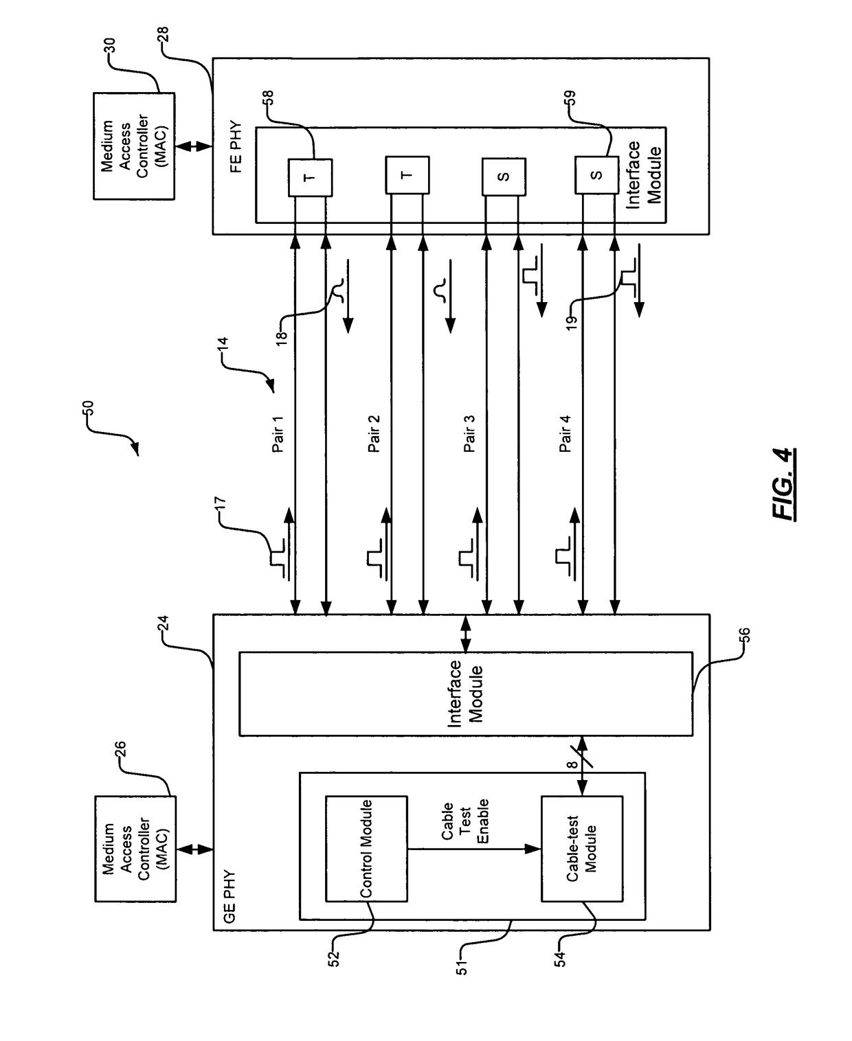
[0072]A network device generally comprises a physical layer module (PHY) and a medium access controller (MA...


PUM


Abstract

A physical layer module (PHY) of a network device includes a control module and a cable-test module. The control module selectively generates a cable-test enable signal to test a cable including four pairs of twisted wire. The cable-test module tests the cable based on the cable-test enable signal. The cable-test module transmits test signals on the four pairs at a first time and receives return signals. The cable-test module determines that the cable is not faulty when the return signals received on first and second pairs of the four pairs have an amplitude less than a first predetermined amplitude, and when the return signals received on third and fourth pairs of the four pairs have an amplitude greater than a second predetermined amplitude and are received substantially contemporaneously.

Description

CROSS-REFERENCE TO RELATED APPLICATIONS[0001]This application claims the benefit of U.S. Provisional Application No. 60 / 812,236, filed Jun. 9, 2006. The disclosure of the above application is incorporated herein by reference in its entirety.FIELD[0002]The present disclosure relates to cable diagnostic systems, and more particularly to diagnostic systems for testing network cables.BACKGROUND[0003]The background description provided herein is for the purpose of generally presenting the context of the disclosure. Work of the presently named inventors, to the extent it is described in this background section, as well as aspects of the description which may not otherwise qualify as prior art at the time of filing, are neither expressly nor impliedly admitted as prior art against the present disclosure.[0004]One goal of a network manager is to control total cost of ownership of the network. Cabling problems can cause a significant amount of network downtime and can require troubleshooting...

Claims


Application Information

Patent Timeline
IPC IPC(8): G01R31/11
CPCH04L12/2697H04L43/50
Inventor ORR, MICHAEL
Owner MARVELL ASIA PTE LTD
Why Eureka
Try Eureka