Image forming apparatus
a technology of image forming apparatus and forming device, which is applied in the direction of electric variable regulation, process and machine control, instruments, etc., can solve the problems of insufficient heat supply to the influence of the fixing capability of the toner image on the transfer material in the fusing device, and the inability to achieve the fixation performance. , to achieve the effect of enhancing responsiveness, reducing power consumption or energy saving, and improving accuracy
- Summary
- Abstract
- Description
- Claims
- Application Information
AI Technical Summary
Benefits of technology
Problems solved by technology
Method used
Image
Examples
embodiment 1-1
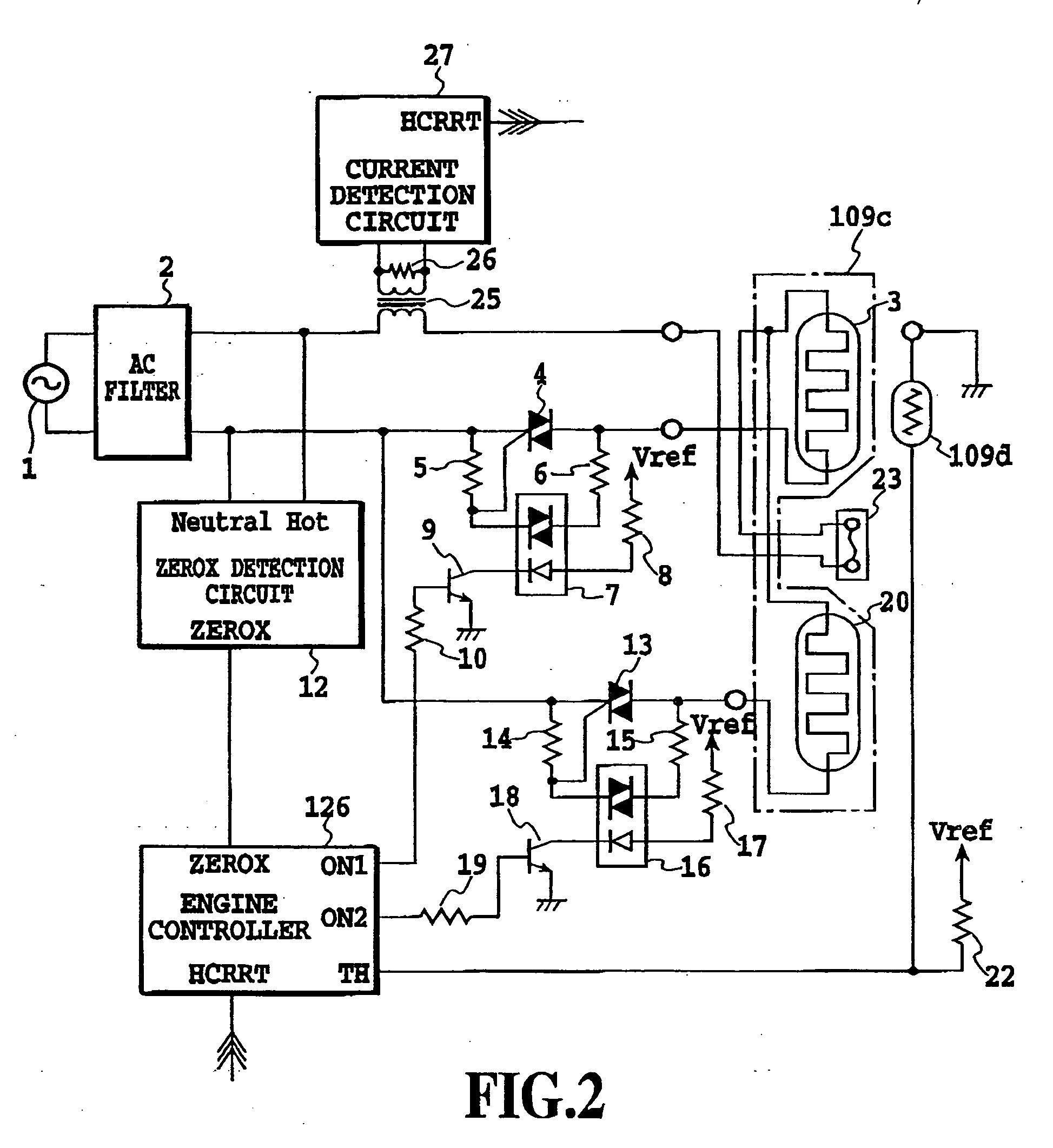
[0063]FIG. 2 is a block diagram of embodiment 1-1 of this invention. This represents an example temperature control circuit to control a temperature of a ceramic planar heater as a heat source of the fusing device. A construction of a laser beam printer incorporating this temperature control circuit is shown in FIG. 3.
[0064]FIG. 3 is explained in the following. A laser beam printer 101 has a cassette 102 accommodating print paper S, a cassette sensor 103 for detecting the presence or absence of print paper S in the cassette 102, a cassette size sensor 104 (made up of a plurality of microswitches) for detecting the size of the print paper S in the cassette 102, and a feed roller 105 for feeding print paper S from the cassette 102.
[0065] Arranged downstream of the feed roller 105 is a resist roller pair 106 for synchronously transporting the print paper S. Downstream of the resist roller pair 106 is installed an image forming unit 108 that forms a toner image on the print paper S ac...
embodiment 1-2
[0093]FIG. 9 is a flow chart showing an outline of a control sequence for the fusing device in this embodiment. In FIG. 9 steps S501 to S504 are the same as in FIG. 6 A to E of FIG. 10 and A to E of FIG. 11 illustrate schematic operation waveforms of a heater current and ON1 and ON2 signals. A to E of FIG. 10 represent operation waveforms when an input voltage is low within the predetermined voltage range. A to E of FIG. 11 represent operation waveforms when the input voltage is high. In the following description, we will refer only to the operation waveforms of A to E of FIG. 10.
[0094] When a request to start power supply to the ceramic planar heater 109c occurs (step S501), the engine controller 126 energizes the heating bodies 3, 20 with the same, fixed duty D1 (S502). At a phase angle α1 corresponding to the fixed duty D1, ON-pulses of ON1 and ON2 signals with a ZEROX signal as a trigger are issued from the engine controller 126 (see B and C of FIG. 10). The ceramic planar heat...
embodiment 2-1
[0124] (1) Example of Image Forming Apparatus
[0125]FIG. 12 is a schematic diagram showing an image forming apparatus in this embodiment. This image forming apparatus is a laser beam printer based on a transfer electrophotographic process
[0126] Denoted 2101 is a photosensitive drum carrying electrostatic charges and 2105 is a laser scanner as an image exposing device. In this laser scanner, reference number 2102 represents a semiconductor laser as a light source, 2103 a rotatable multi-faced mirror that is rotated by a scanner motor 2104, and L a laser beam emitted from the semiconductor laser 2102 and adapted to scan over the photosensitive drum 2101.
[0127] Designated 2106 is a charge roller 2106 to uniformly charge the surface of the photosensitive drum 2101. The surface of the photosensitive drum 2101 uniformly charged by the charge roller 2106 is scanned and exposed by the output leaser beam L from the laser scanner 2102 to form an electrostatic latent image of target image in...
PUM
 Abstract
Description
Claims
Application Information
 - R&D
- Intellectual Property
- Life Sciences
- Materials
- Tech Scout
- Unparalleled Data Quality
- Higher Quality Content
- 60% Fewer Hallucinations
Browse by: Latest US Patents, China's latest patents, Technical Efficacy Thesaurus, Application Domain, Technology Topic, Popular Technical Reports.
© 2025 PatSnap. All rights reserved.Legal|Privacy policy|Modern Slavery Act Transparency Statement|Sitemap|About US| Contact US: help@patsnap.com


