Magnetic measurement apparatus

a technology of magnetic measurement and measuring device, which is applied in the field of magnetic measurement device, can solve the problem of inability to perform high-accuracy magnetic measurement, and achieve the effect of improving measurement accuracy

Active Publication Date: 2015-12-31
RENESAS ELECTRONICS CORP
View PDF1 Cites 85 Cited by
  • Summary
  • Abstract
  • Description
  • Claims
  • Application Information

AI Technical Summary

Benefits of technology

[0008]In this case, a magnetic field is measured as the positional change of a “valley” corresponding to a minimum fluorescence intensity value of this waveform. Therefore, the narrower and deeper the “valley” becomes, the higher the measurement accuracy becomes. However, a waveform originating from each nitrogen-vacancy pair has “valleys” at different positions with respect to the four types of orientations of the vacancy when viewed from the nitrogen.
[0009]For this reason, in general, a measured waveform is the superimposition of the “valleys” at these four different types of positions. Thus, the number of nitrogen-vacancy pairs

Problems solved by technology

This may make it impossible to perfor

Method used


Image

  • Magnetic measurement apparatus
  • Magnetic measurement apparatus
  • Magnetic measurement apparatus

Examples


first embodiment

[0038]

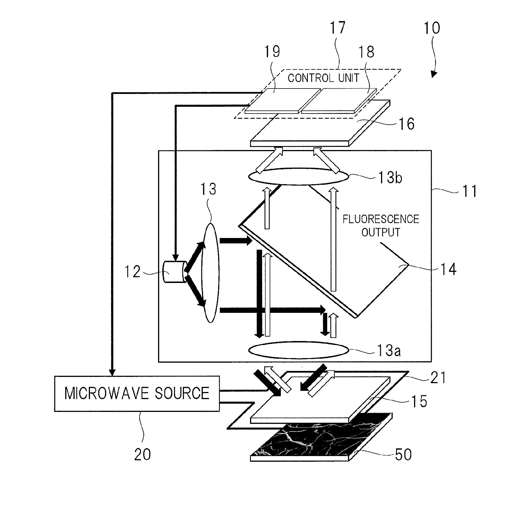
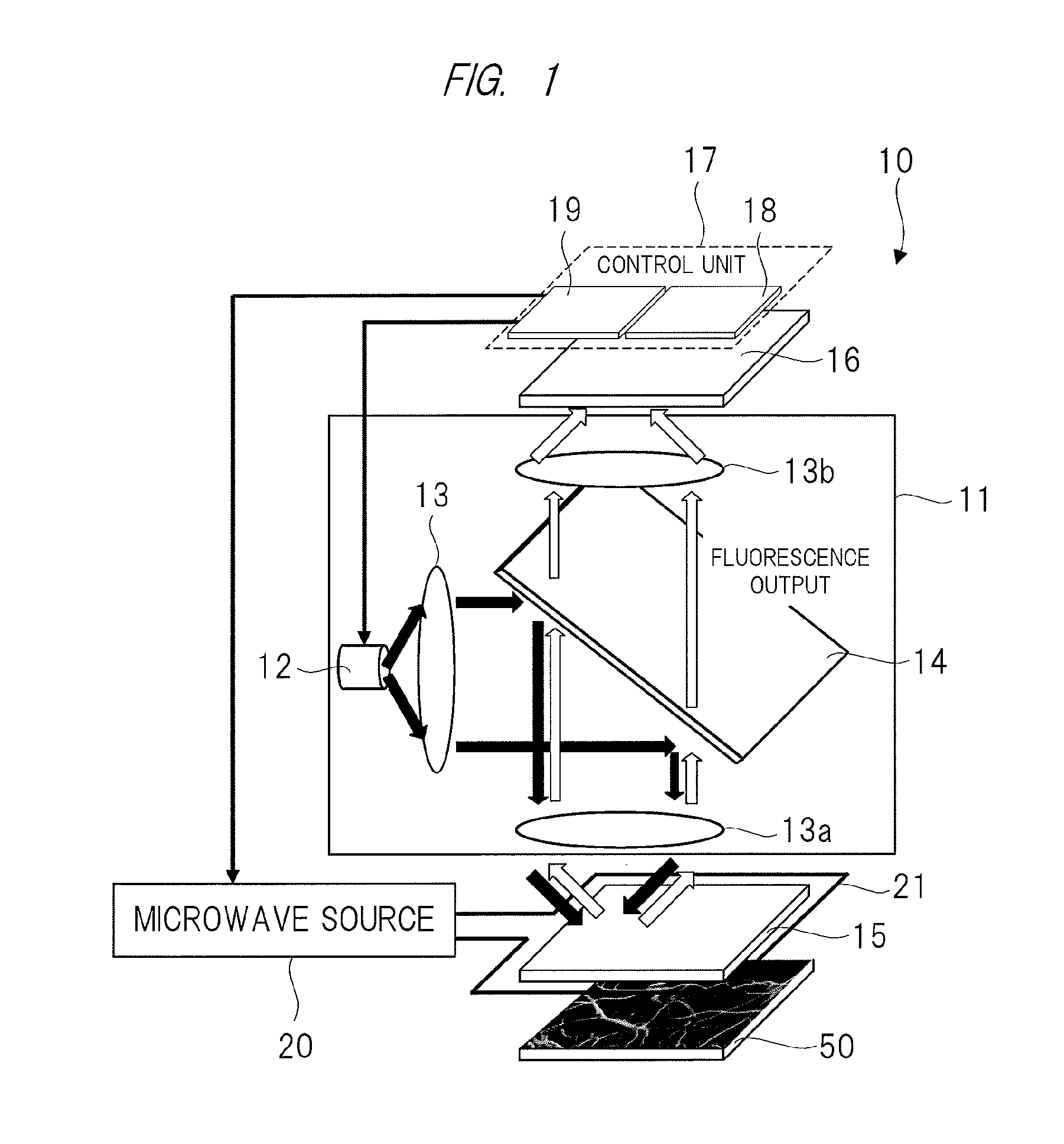
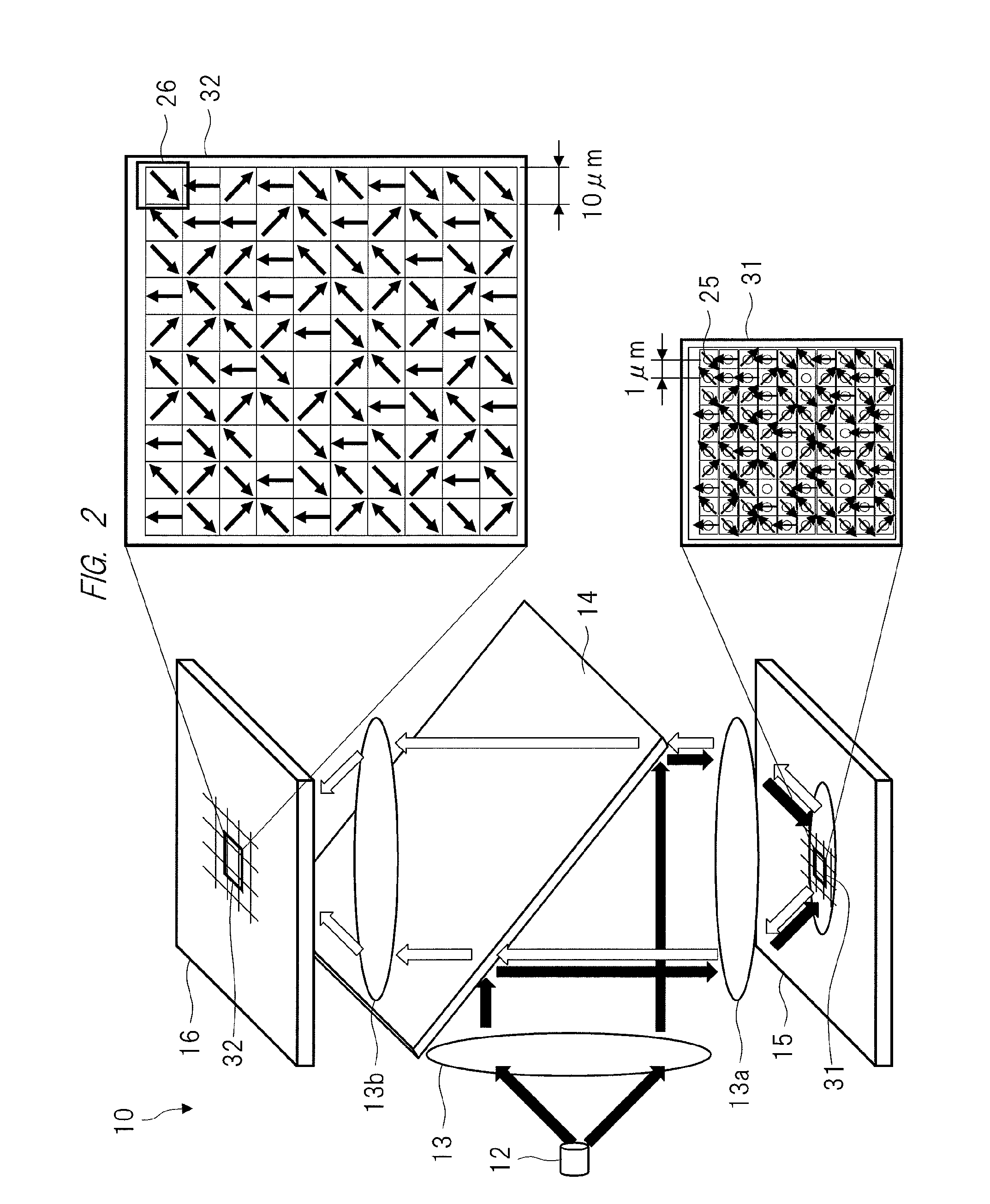
[0039]According to a brief description of this embodiment, in a magnetic measurement apparatus 10, the positions of nitrogen-vacancy pairs 25 in a diamond crystal 15 one-to-one correspond to the positions of pixels 26 of an image sensor 16 which measures fluorescence outputs from the nitrogen-vacancy pairs 25. In other words, the image sensor 16 is provided such that fluorescence generated by a given one of the nitrogen-vacancy pairs 25 is received by one pixel 26 made to correspond to the nitrogen-vacancy pair 25.

[0040]In addition, the magnetic measurement apparatus 10 is calibrated in advance for each nitrogen-vacancy pair so as to specify what type of orientation the vacancy of each nitrogen-vacancy pair 25 has when viewed from the nitrogen with respect to the diamond crystal orientation. The magnetic measurement apparatus 10 is configured to measure a magnetic field so as to improve the measurement accuracy by efficiently using all the nitrogen-vacancy pairs having four ty...

second embodiment

[0137]

[0138]The magnetic measurement apparatus 10 in FIG. 6 according to the above first embodiment is configured to implement a spatial resolution on a pixel basis in the image sensor 16. In contrast to this, a second embodiment will exemplify a case in which a spatial resolution is implemented on a block basis in an image sensor 16.

[0139]

[0140]FIG. 11 is an explanatory view showing an example of the configuration of a magnetic measurement apparatus 10 according to the second embodiment.

[0141]The magnetic measurement apparatus 10 in FIG. 11 implements a spatial resolution on a block basis in the image sensor 16 by performing negative feedback control with respect to a pixel output from the image sensor 16 as a frequency modulation input to a microwave source 20.

[0142]The magnetic measurement apparatus 10 in FIG. 11, as in FIG. 6, includes a blue-green light source 12, a lens 13, a dichroic mirror 14, a diamond crystal 15, the image sensor 16, a control unit 17, a microwave source 2...

third embodiment

[0154]

[0155]FIG. 13 is an explanatory view showing an example of the configuration of a magnetic measurement apparatus 10 according to a third embodiment.

[0156]The magnetic measurement apparatus 10 shown in FIG. 13 is provided with a high-frequency circuit chip 27 as an irradiation unit in place of the microwave source 20 in the configuration of FIG. 11 in the second embodiment. In addition, a control unit 17 is constituted by a signal processing array 60 and a control circuit 19.

[0157]The signal processing array 60 includes a plurality of signal processing units 61. Each signal processing unit 61 is constituted by a signal processing circuit 18 and an operation unit OPN which are shown in FIG. 11. Note that FIG. 13 shows the connection relationship between the three signal processing units 61 as a typical example. In practice, the signal processing units 61 are respectively provided for the blocks 41 of an image sensor 16.

[0158]

[0159]FIG. 14 is an explanatory view showing an exampl...


PUM


Abstract

High-accuracy magnetic measurement is performed by efficiently using nitrogen-vacancy pairs in all orientations. A magnetic measurement apparatus includes a diamond crystal and an image sensor. The diamond crystal has nitrogen-vacancy pairs. The image sensor detects the intensities of fluorescence generated by an exciting light applied to the diamond crystal by using a plurality of pixels. The nitrogen-vacancy pairs of the diamond crystal are made to one-to-one correspond to the pixels. The fluorescence generated by one nitrogen-vacancy pair is received by one pixel made to correspond to the nitrogen-vacancy pair.

Description

CROSS-REFERENCE TO RELATED APPLICATION[0001]The present application claims priority from Japanese Patent Application No. 2014-131944 filed on Jun. 26, 2014, the content of which is hereby incorporated by reference into this application.TECHNICAL FIELD OF THE INVENTION[0002]The present invention relates to a magnetic measurement apparatus and, more particularly, to a technique effective in detecting a magnetic field in a room temperature atmosphere by using nitrogen-vacancy pairs of a diamond crystal.BACKGROUND OF THE INVENTION[0003]As a biomagnetic measurement system as medical equipment, for example, a magnetoencephalography system is known. The magnetoencephalography system is a system which accurately examines an active region and the degree of activity in the brain by externally measuring a weak magnetic field generated by neurons.[0004]A biomagnetic measurement system of this type includes a high-sensitivity magnetic measurement apparatus. As this high-sensitivity magnetic meas...

Claims


Application Information

Patent Timeline
IPC IPC(8): A61B5/04A61B5/00
CPCA61B5/04008A61B5/0071G01R33/1284G01R33/0094G01R33/032C30B29/04A61B5/245
Inventor HATANO, YUJIYAMADA, KOJIYOSHINO, TAKASHI
Owner RENESAS ELECTRONICS CORP
Why Eureka
Try Eureka