Lighting control system and method

a control system and lighting technology, applied in the field of power utilities, can solve the problem that the control has been limited to traditional lighting aspects

Inactive Publication Date: 2010-10-14
LUMETRIC LIGHTING
View PDF99 Cites 121 Cited by
  • Summary
  • Abstract
  • Description
  • Claims
  • Application Information

AI Technical Summary

Benefits of technology

[0007]In one embodiment of the invention, an apparatus for control of a powered utility is disclosed. The apparatus comprises a processor capable of altering a state of the powered utility. The apparatus additionally comprises a data port configured to transmit a set of messages, which include a message delivered from the processor. In addition, the data port on the apparatus is configured to autonomously form a network communication channel with a similar apparatus.
[0008]In another embodiment of the invention, a system for control of a set of powered utilities is disclosed. The system comprises a first device comprising a first processor capable of altering a first state of a first powered utility. The first device further comprises a first data port configured to transmit a set of messages which include a

Problems solved by technology

To date, such control has been limited to traditional lighting aspects, such as activity sensors to illuminate an area only when it is occupied, timer mec

Method used


Image

  • Lighting control system and method
  • Lighting control system and method
  • Lighting control system and method

Examples


Embodiment Construction

[0019]Reference now will be made in detail to embodiments of the disclosed invention, one or more examples of which are illustrated in the accompanying drawings. Each example is provided by way of explanation of the present technology, not as a limitation of the present technology. In fact, it will be apparent to those skilled in the art that modifications and variations can be made in the present technology without departing from the spirit and scope thereof. For instance, features illustrated or described as part of one embodiment may be used with another embodiment to yield a still further embodiment. Thus, it is intended that the present subject matter covers such modifications and variations as are within the scope of the appended claims and their equivalents.

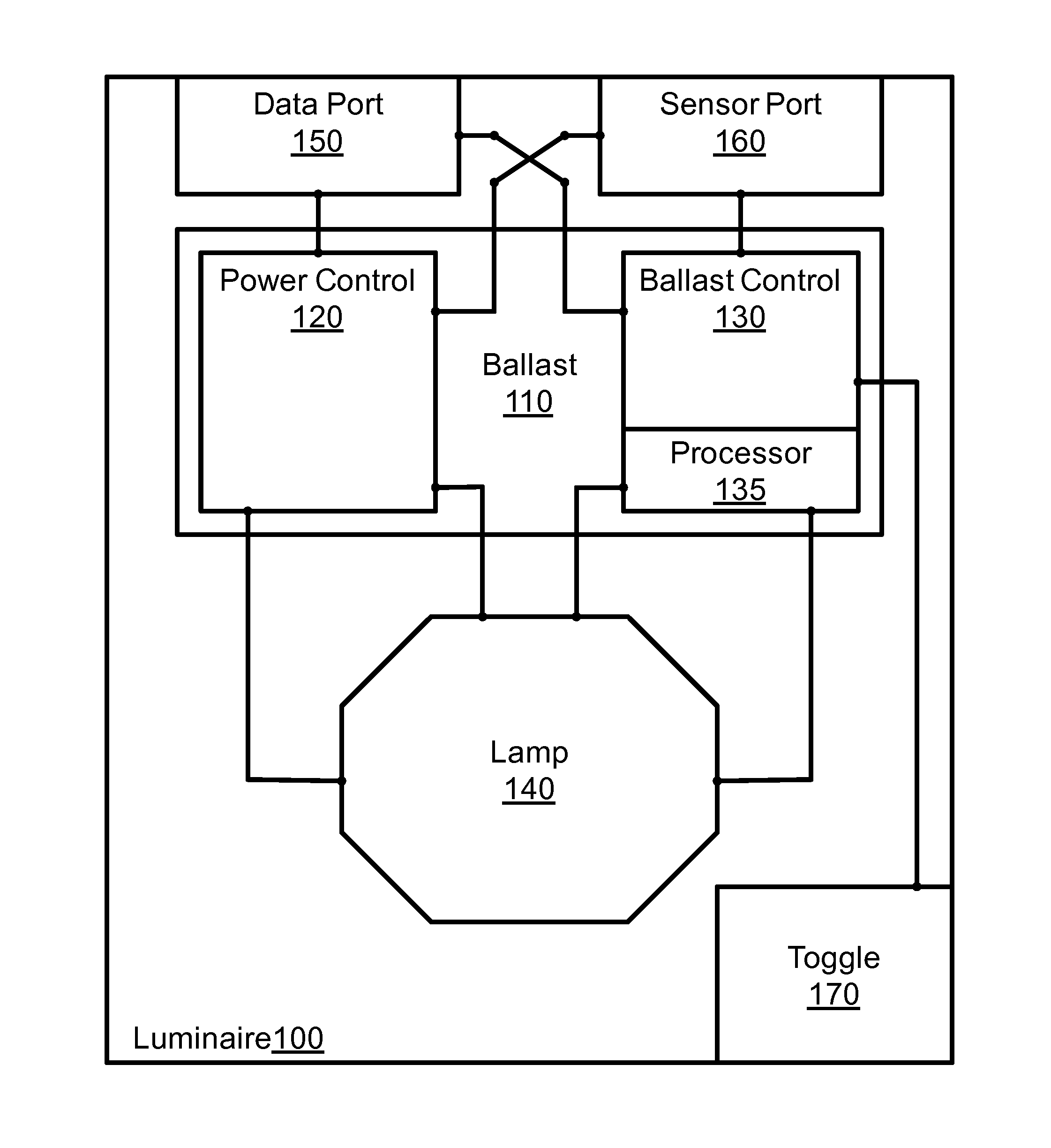
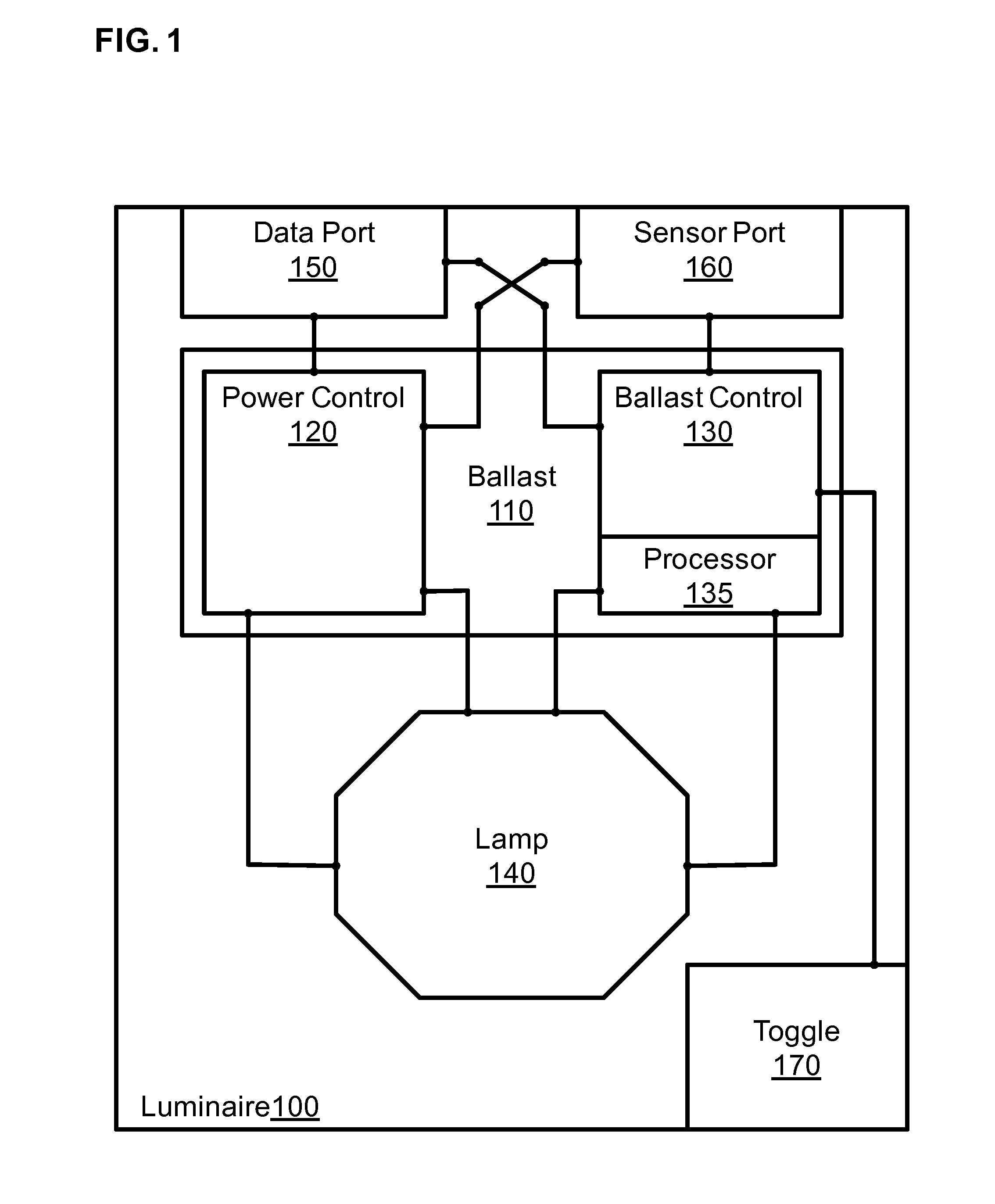
[0020]A device such as a lighting or HVAC utility that is in accordance with the present invention is augmented with a processor that enables it to independently or cumulatively; obtain sensor data and event data, receive ...


PUM


Abstract

A system for the control of a set of powered utilities is disclosed. The system comprises a first device which in turn comprises a processor capable of altering a state of a first powered utility. This first device further comprises a data port configured to transmit a set of messages. These messages include a transmitted message delivered from the processor. The system additionally comprises a second device which in turn comprises a second processor capable of altering a state of a second powered utility. The second processor is configured to selectively alter the state of the second powered utility based on the transmitted message.

Description

CROSS-REFERENCE TO RELATED APPLICATIONS[0001]This patent application is a continuation-in-part of U.S. patent application Ser. No. 12 / 482,570 filed Jun. 11, 2009, which claims the benefit of U.S. Provisional Patent No. 61 / 075,371 filed Jun. 25, 2008. The contents of U.S. patent application Ser. No. 12 / 482,570 and U.S. Provisional Patent No. 61 / 075,371 are incorporated herein by reference.FIELD OF THE INVENTION[0002]The invention described relates generally to the control of powered utilities, and more specifically to the control of lighting devices with onboard processing capabilities.BACKGROUND OF THE INVENTION[0003]Recent advances in ballast-controlled lighting devices have led to the availability of programmable luminaires. Some of these devices include microprocessors for control of the devices, e.g., providing automated dimming capabilities and power management features.[0004]On-board processing capabilities allow local control of certain operating parameters. To date, such con...

Claims


Application Information

Patent Timeline
IPC IPC(8): G05B15/00
CPCG05B15/02H05B37/0254G05B2219/2642H05B47/18
Inventor DAVIS, GREGORYSHLOUSH, MOSHE
Owner LUMETRIC LIGHTING
Why Eureka
Try Eureka