Door With A Rotatable Shell Wall

Inactive Publication Date: 2010-10-21
PESSERS HENRICUS JOHANNES RAYMUNDUS ANTONIUS
View PDF12 Cites 0 Cited by
  • Summary
  • Abstract
  • Description
  • Claims
  • Application Information

AI Technical Summary

Benefits of technology

[0014]In this way the influence of the wind conditions can be further suppressed.
[0015]It is advantageous that the wind deflectors are movable in respect of the rotatable shell wall. This allows for adjustment of the wind deflectors to better meet the prevailing weather conditions.
[0016]To promote a quick and easy adjustment to the weathe

Problems solved by technology

The known door is not particularly suited to allow the passage of larger groups of people in

Method used


Image

  • Door With A Rotatable Shell Wall
  • Door With A Rotatable Shell Wall
  • Door With A Rotatable Shell Wall

Examples


Example

[0034]Wherever in the figures the same reference numerals are applied these reference numerals refer to similar parts of the door of the invention.

DETAILED DESCRIPTION OF THE INVENTION

[0035]The above-described drawing figures illustrate the invention, a door 2 including a rotatable shell wall 7.

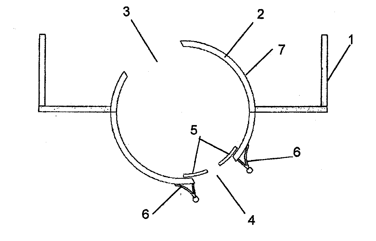
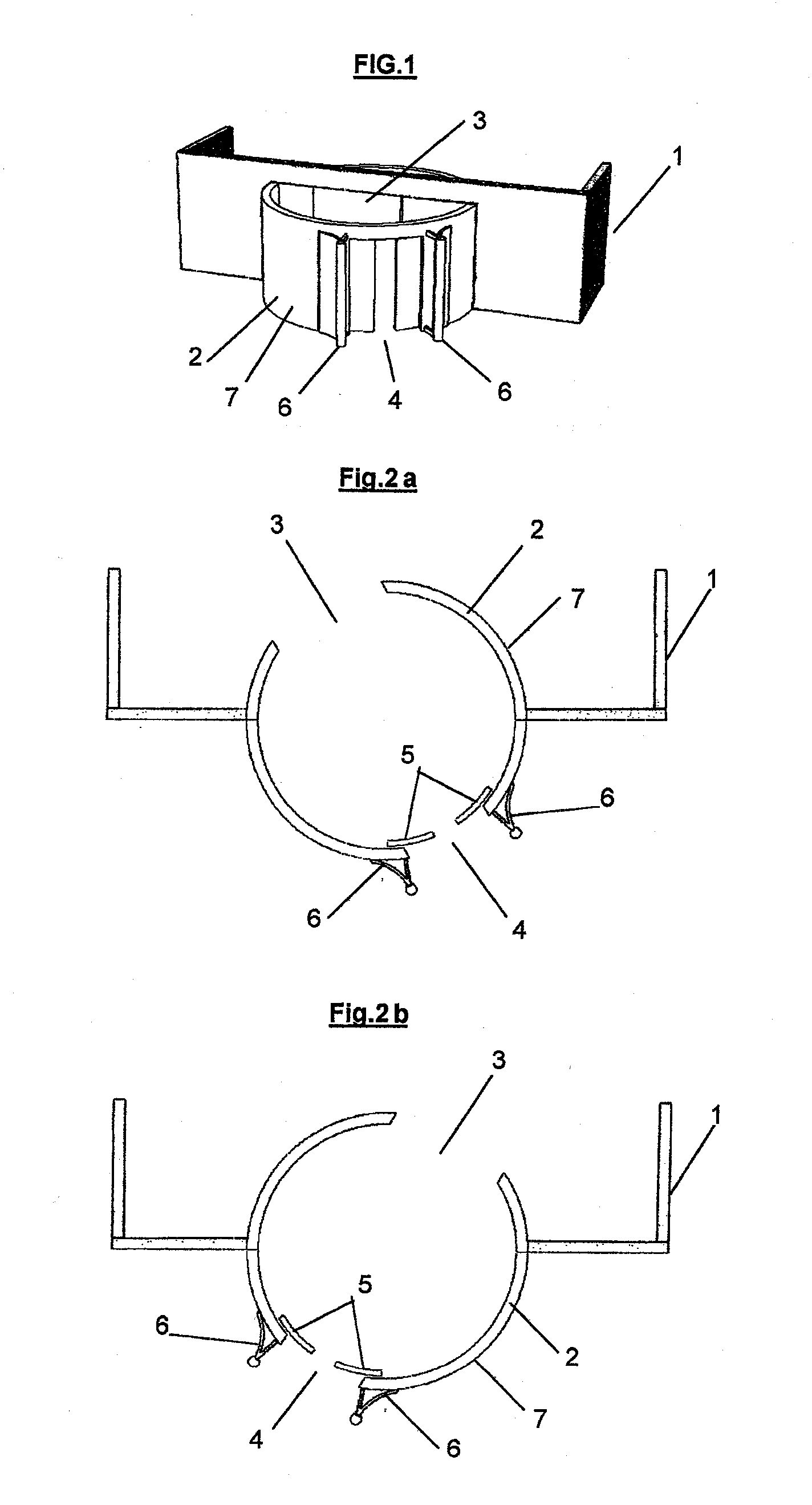
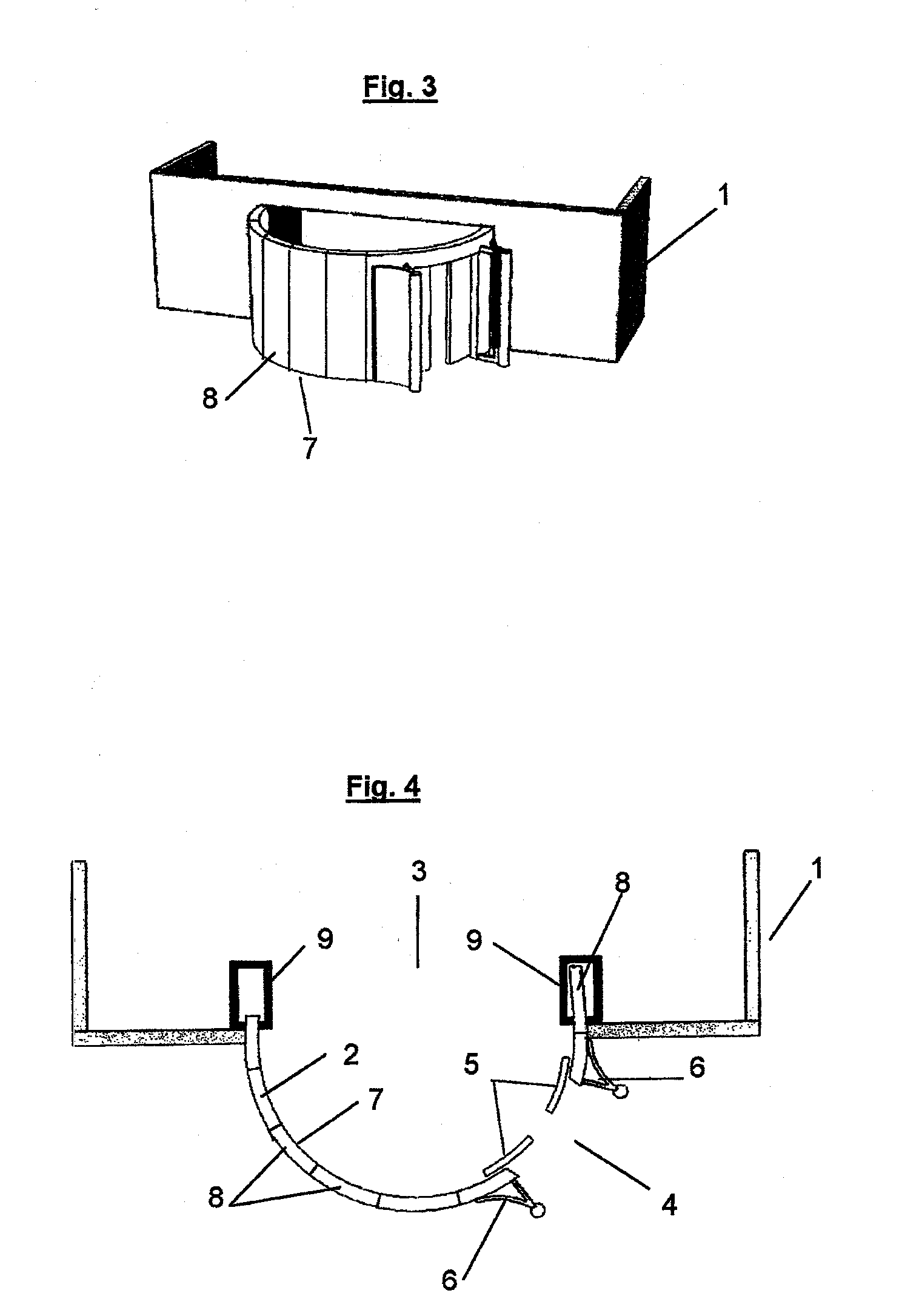
[0036]With reference first to FIG. 1 a part of an outside facade of a building 1 is shown in which the door 2 according to the invention is applied. This door 2 comprises the rotatable shell wall 7, which shell wall 7 is, as FIG. 1 clearly shows, at least in part cylindrically shaped. The door 2 is further provided with an entrance 4 and an exit 3 as is more clearly shown in FIGS. 2a and 2b.

[0037]The rotatable shell wall 7 is rotatable to a preselected stationary position, two of which are shown in FIG. 2a and FIG. 2b, respectively.

[0038]At these stationary positions, such as shown in FIG. 2a and FIG. 2b, the rotatable shell wall 2 can be arrested with an arresting element in order to realis...


PUM


Abstract

A door has a rotatable shell wall that is at least in part cylindrically shaped and is provided with an entrance and an exit. The rotatable shell wall is rotatable to a preselected stationary position at which the rotatable shell wall can be arrested and at which stationary position the door is usable for both ingress and egress.

Description

BACKGROUND OF THE INVENTION[0001]1. Field of the Invention[0002]The invention relates to a door comprising a rotatable shell wall which shell wall at least in part is cylindrically shaped and is provided with an entrance and an exit.[0003]2. Description of Related Art[0004]A similar door is shown in DE-C-199 05 473. In the known door, the shell wall continuously rotates in order to intermittently give way to the entrance respectively the exit of the door, whilst continuously maintaining a draft resistant closure of the building in which the door is applied. The known door is not particularly suited to allow the passage of larger groups of people in view of the fact that at the time the entrance is open the exit will be closed and vice versa.SUMMARY OF THE INVENTION[0005]The present invention teaches certain benefits in construction and use which give rise to the objectives described below.[0006]The invention has as an object to provide a door which is better suited to meet the handl...

Claims


Application Information

Patent Timeline
IPC IPC(8): E05F15/20E06B3/36
CPCE06B3/90
Inventor PESSERS, HENRICUS JOHANNES RAYMUNDUS ANTONIUS
Owner PESSERS HENRICUS JOHANNES RAYMUNDUS ANTONIUS
Why Eureka
Try Eureka