Backflow prevention circuit and power supply circuit

Active Publication Date: 2019-12-26
ABLIC INC
View PDF0 Cites 1 Cited by
  • Summary
  • Abstract
  • Description
  • Claims
  • Application Information

AI Technical Summary

Benefits of technology

[0017]According to the present invention, it is possible to suppress the influence caused by a process or temperature characteristics and prevent tire reverse current flow without adding the step of controlling or managing the process where the forwa

Problems solved by technology

Consequently, the manufacturing cost

Method used


Image

  • Backflow prevention circuit and power supply circuit
  • Backflow prevention circuit and power supply circuit
  • Backflow prevention circuit and power supply circuit

Examples


Example

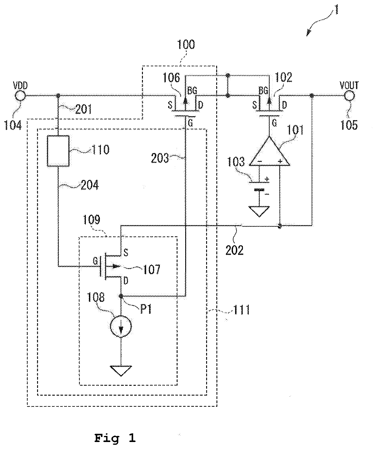
[0029]Hereinafter, description is given of a first embodiment of the present invention with reference to the drawings. FIG. 1 is a schematic block diagram for illustrating a voltage regulator 1 serving as a power supply circuit according to the first embodiment, including a backflow prevention circuit according to the first embodiment.

[0030]The voltage regulator 1 includes a backflow prevention circuit 100, an error amplifier 101, an output-stage transistor 102, and a reference voltage source 103. The backflow prevention circuit 100 includes a backflow prevention transistor 106 and a backflow prevention control circuit 111. The backflow prevention control circuit 111 includes a constant current inverter 109 and a level shift circuit 110. The constant current inverter 109 includes a first transistor 107 and a constant current circuit 108 serving as a first current source circuit. In the constant current inverter 109, the first transistor 107 is connected with the constant current c...

Example

Second Embodiment

[0070]Hereinafter, description is given of a second embodiment of the present invention with reference to the drawing. FIG. 5 is a schematic diagram for illustrating a circuit example of a level shift circuit 110A in a backflow prevention circuit according to the second embodiment. The backflow prevention circuit according to the second embodiment is the same configuration as that of the first embodiment except for the level shift circuit 110A.

[0071]The level shift circuit 110A includes a constant current circuit 112 and a PMOS transistor 114. The PMOS transistor 114 is used in place of the resistor 113 in the level shift circuit 110 (illustrated in FIG. 2). Further, the constant current circuit 112 is the same as that of the first embodiment.

[0072]The PMOS transistor 114 contains a source S connected to a wiring 201, and a gate G and a drain D connected to a wiring 204.

[0073]Here, if a current I112 flows through the constant current circuit 112, and a threshold vol...

Example

Third Embodiment

[0076]Hereinafter, description is given of a third embodiment of the present invention with reference to the drawing. FIG. 6 is a schematic diagram for illustrating a circuit example of a level shift circuit 110B in a backflow prevention circuit according to the third embodiment. The backflow prevention circuit according to the third embodiment is the same configuration as that of the first embodiment except for the level shift circuit 110B.

[0077]The level shift circuit 110B includes a constant current circuit 112 and a diode 115 serving as a PN junction element. In the third embodiment, the diode 115 is used in place of the resistor 113 in the level shift circuit 110 (illustrated in FIG. 2). The constant current circuit 112 is similar to that of the first embodiment.

[0078]The diode 115 contains an anode connected to a wiring 201, and a cathode connected to a wiring 204.

[0079]Here, if the current I112 flows through the constant current circuit 112, and a forward volt...


PUM


Abstract

Provided is a backflow prevention circuit including a backflow prevention transistor as a p-channel MOS transistor interposed in series between an input terminal to which a power supply voltage is supplied, and an output-stage transistor as a p-channel MOS transistor, configured to supply an output voltage from an output terminal, and a backflow prevention control circuit configured to turn off the backflow prevention transistor if the output voltage exceeds the power supply voltage. The backflow prevention control circuit includes a first transistor, a first current source circuit, and a level shift circuit.

Description

RELATED APPLICATIONS[0001]Priority is claimed on Japanese Patent Application No. 2018-119939, filed on Jun. 25, 2018, the content of which is incorporated herein by reference.BACKGROUND OF THE INVENTION1.Field of the Invention[0002]The present invention relates to a backflow prevention circuit and a power supply circuit.2. Description of the Related Art[0003]A step-down voltage regulator is used in a state in which an input voltage is maintained higher than an output voltage. However, depending on use conditions and a circuit structure, there is a case where the output voltage becomes higher than the input voltage. In this case, there may be a situation in that a current flow back from an output terminal.[0004]To cope with this situation, there has been proposed a structure in which a p-channel metal oxide semiconductor (MOS) transistor in an output stage of the voltage regulator is turned off if the output voltage is detected to be higher than the input voltage so that a reverse cu...

Claims


Application Information

Patent Timeline
IPC IPC(8): H02H3/00H03K19/0185
CPCH03K19/018507H02H3/003G05F1/56H02H3/18G05F1/569
Inventor TOMIOKA, TSUTOMUKURODA, TADAKATSU
Owner ABLIC INC
Why Eureka
Try Eureka