Image pickup apparatus, lens unit, and methods of controlling image pickup apparatus and lens unit

Active Publication Date: 2014-10-09
CANON KK
View PDF6 Cites 1 Cited by
  • Summary
  • Abstract
  • Description
  • Claims
  • Application Information

AI Technical Summary

Benefits of technology

[0008]The present invention provides an image pickup apparatus, a lens unit, and methods of controlling the image pickup apparatus and the lens

Problems solved by technology

Due to this drawback, some interchangeable lenses designed to be mounted on an image pickup apparatus may not be able to satisfy an in-focus accuracy allowable as a still image.
If an image pickup apparatus stores a correction values (hereinafter, referred to as a “best focus (BF) correction value”) designed to corre

Method used


Image

  • Image pickup apparatus, lens unit, and methods of controlling image pickup apparatus and lens unit
  • Image pickup apparatus, lens unit, and methods of controlling image pickup apparatus and lens unit
  • Image pickup apparatus, lens unit, and methods of controlling image pickup apparatus and lens unit

Examples


Example

First Embodiment

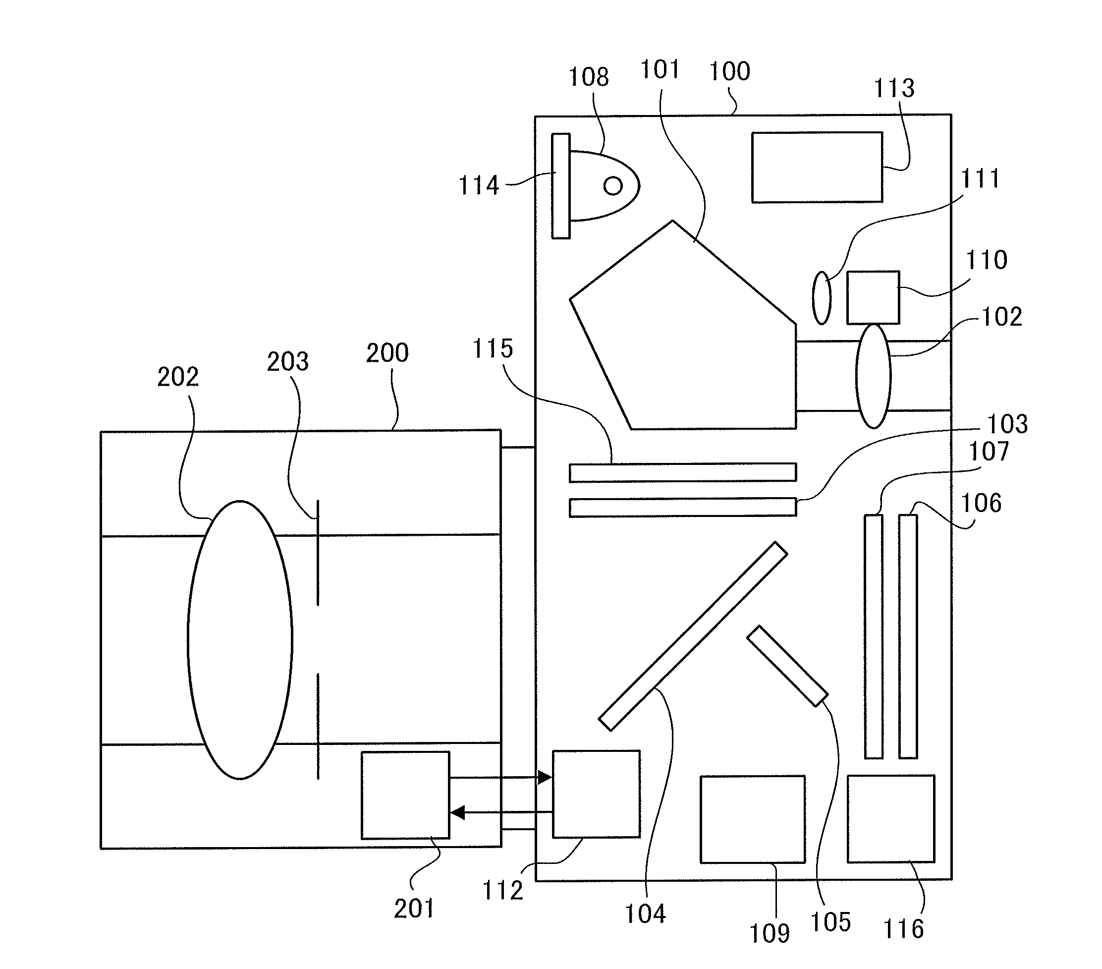
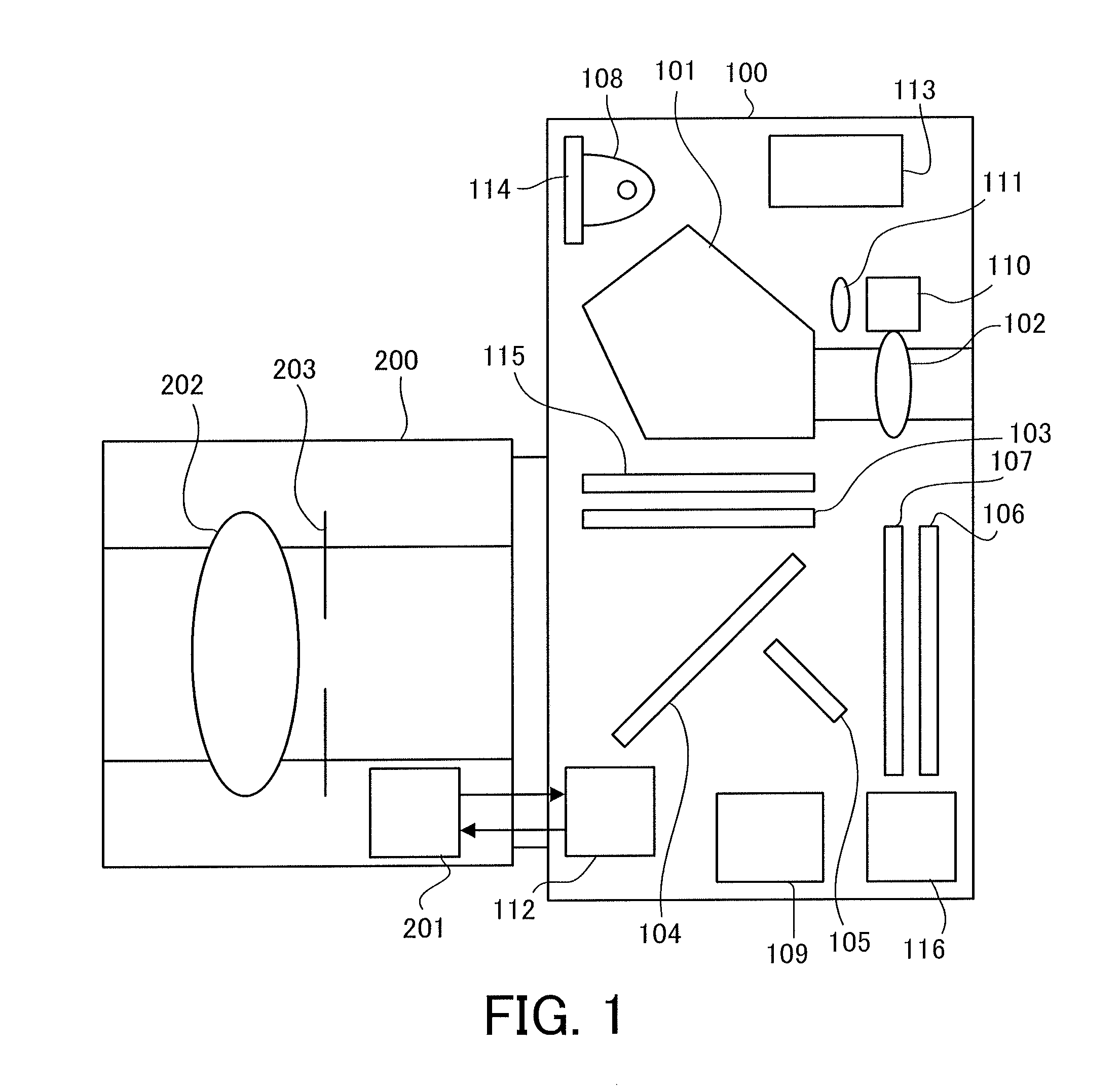
[0029]First of all, referring to FIG. 1, the configuration of an image pickup system in the first embodiment of the present invention will be described. FIG. 1 is a schematic configuration diagram of the image pickup system in this embodiment.

[0030]In FIG. 1, the image pickup system includes an image pickup apparatus 100 (an image pickup apparatus body, or a camera) and an interchangeable lens 200 (a lens unit) removably mounted on the image pickup apparatus 100. As described later, the image pickup apparatus 100 include an image pickup element with a plurality of pixels, each of which has a plurality of photodiodes arranged underneath a micro lens, and the photodiodes receive light from pupil regions (divided pupil regions) different from each other in an image pickup optical system including a lens 202. In this configuration, the image pickup apparatus 100 is capable of performing a focus detection method by using a phase difference detection method (an imaging pla...

Example

Second Embodiment

[0098]Next, referring to FIGS. 7 and 8, the second embodiment of the present invention will be described. This embodiment relates to second selection processing of an AF method in which a user can register a focus correction value, which is performed instead of the first selection processing of the AF method performed at step S302 of FIG. 3.

[0099]FIG. 7 is a flowchart illustrating a procedure of the second selection processing of the AF method in this embodiment. Each step of FIG. 7 is mainly performed based on a command (an instruction) of the controller 112 (the camera CPU). FIG. 7 is different from the flowchart of FIG. 6 (the first embodiment) in that steps S703, S719, and S720 are added. Since the steps S701, S702, S704 to S718, and S721 are the same as steps S601 to S618 of FIG. 6 respectively, the description thereof will be omitted.

[0100]Subsequently to step S702, at step S703, the controller 112 (a registration unit) determines whether or not a focus correc...


PUM


Abstract

An image pickup apparatus on which a lens unit is to be removably mounted includes an image pickup element, a first focus detection unit which performs a focus detection by a contrast detection method based on a signal output from the image pickup element, a second focus detection unit which performs a focus detection by a phase difference detection method based on a pair of image signals output from the image pickup element, and a control unit which performs a focus control based on an in-focus position detected by the first or second focus detection unit, and the control unit receives, from the mounted lens unit, first information related to a displacement of the in-focus position by the phase difference detection method and determines whether to use the second focus detection unit for the focus control according to the first information.

Description

BACKGROUND OF THE INVENTION[0001]1. Field of the Invention[0002]The present invention relates to an image pickup apparatus including different types of focus detection units.[0003]2. Description of the Related Art[0004]Conventionally, as focus detection methods of an image pickup apparatus, a phase difference detection method which detects a pair of image signals obtained from a light beam that has passed through different pupil regions of an optical system and a contrast detection method which uses a contrast component of an image signal have been known. In addition, as one of the phase difference detection methods, an imaging plane phase difference detection method has been known which performs focus detection by the phase difference detection method by using an output from an image pickup element.[0005]Japanese Patent Laid-Open No. (“JP”) 2001-083407 discloses, as a focus detection method adopting the imaging plane phase difference detection method, a configuration in which each ...

Claims


Application Information

Patent Timeline
IPC IPC(8): H04N5/232H04N5/225
CPCH04N5/2254H04N5/23212H04N23/672H04N23/673H04N25/704H04N25/134G02B7/102G02B7/285G02B7/365G02B7/36G02B7/08H04N23/663
Inventor ODAKA, YUKIOYANO, SHINICHIRO
Owner CANON KK
Why Eureka
Try Eureka