Air conditioning register

a technology for air conditioners and registers, which is applied in the direction of domestic cooling devices, vehicle heating/cooling devices, vehicle components, etc., can solve the problems of difficult to improve the blow-out efficiency of air-conditioned air, and achieve the improvement of the rigidity of the fin, the appearance of the external air blow-out port, and the effect of maintaining rigidity

Inactive Publication Date: 2010-10-21
TOYOTA JIDOSHA KK
View PDF4 Cites 18 Cited by
  • Summary
  • Abstract
  • Description
  • Claims
  • Application Information

AI Technical Summary

Benefits of technology

[0040]In an air conditioning register relating to an aspect of the present invention, at least one longitudinal direction end side of the fin, which is for changing the direction of the air-conditioned air in a direction intersecting the direction of changing the air-conditioned air by the air-direction controlling unit, is provided further toward the inner side of the air blow-out port than the surface of the register design portion. Therefore, the external appearance of the air blow-out port can be improved.
[0041]In an air conditioning register relating to an aspect of the present invention, the reinforcing member is provided at the inner side of the fin which is for changing the direction of the air-conditioned air in a direction intersecting the direction of changing the air-conditioned air by the air-direction controlling unit. The rigidity of the fin can thereby be improved, and therefore, the rigidity can be maintained even if the fin is formed to be long.
[0042]In an air conditioning register relating to an aspect of the present invention, the projecting portion is provided in a vicinity of the opening which is provided in the register design portion. Therefore, sticking of the air-conditioned air to the surface of the register design portion can be prevented or effectively suppressed, and the air-conditioned air can be directed effectively toward the vehicle cabin interior.
[0043]In an air conditioning register relating to an aspect of the present invention, by making the fin operation portion be the projecting portion, it suffices to not especially provide a projecting portion at the register design portion. The parts cost can be reduced, and a deterioration in the external appearance due to the special provision of a projecting portion at the register design portion can be prevented or suppressed.
[0044]In an air conditioning register relating to an aspect of the present invention, the shaft portion, which is provided coaxially with the rotational center of the fin and which is disposed in the hole portion formed in the register main body, is provided at one longitudinal direction end portion of the fin. Therefore, when the fin is rotated, either no gap arises between the end portion of the fin and the surface of the register main body, or such a gap can be made to be small. Therefore, the direction of the air-conditioned air can be changed smoothly and reliably.
[0045]In an air conditioning register relating to an aspect of the present invention, the radius from the rotation axis center to the outer peripheral portion of the shaft portion of the fin is set to be greater than or equal to a distance from the center of rotation of the fin to, among the both transverse direction ends of the fin, the end portion which is furthest from the center of rotation. Therefore, because no gap is made to arise between the end portion of the fin and the surface of the register main body at the time when the fin is rotated, the direction of the air-conditioned air can be changed even more smoothly and reliably.

Problems solved by technology

Therefore, in cases in which the blow-out port is made to be small or the blow-out port is made to be narrow, the proportion of the opening surface area of the blow-out port which is occupied by the fins becomes large, and it may be difficult to improve the blow-out efficiency of the air-conditioned air.

Method used


Image

  • Air conditioning register
  • Air conditioning register
  • Air conditioning register

Examples


first exemplary embodiment

Operation of First Exemplary Embodiment

[0078]The operation of the present exemplary embodiment will be described next.

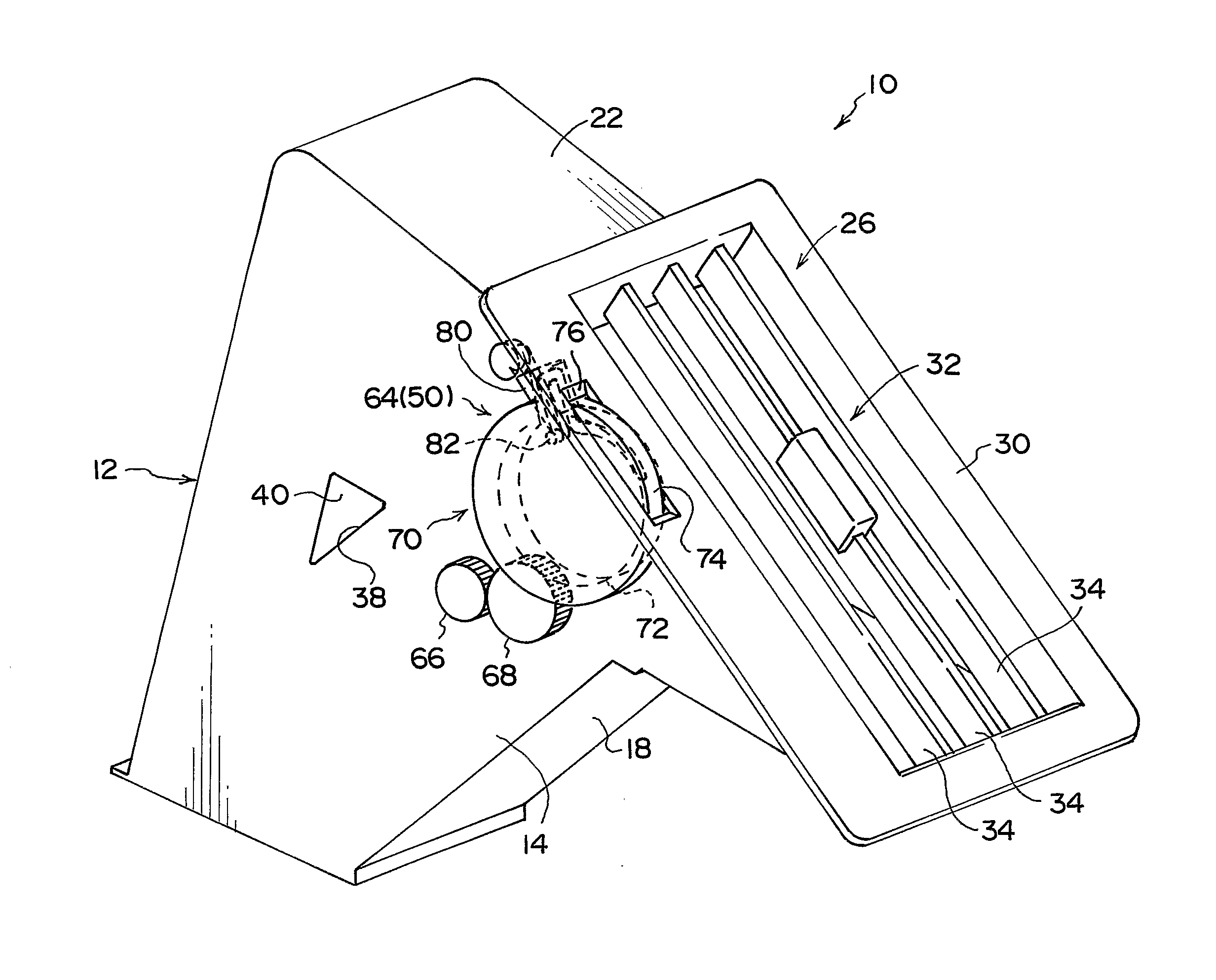
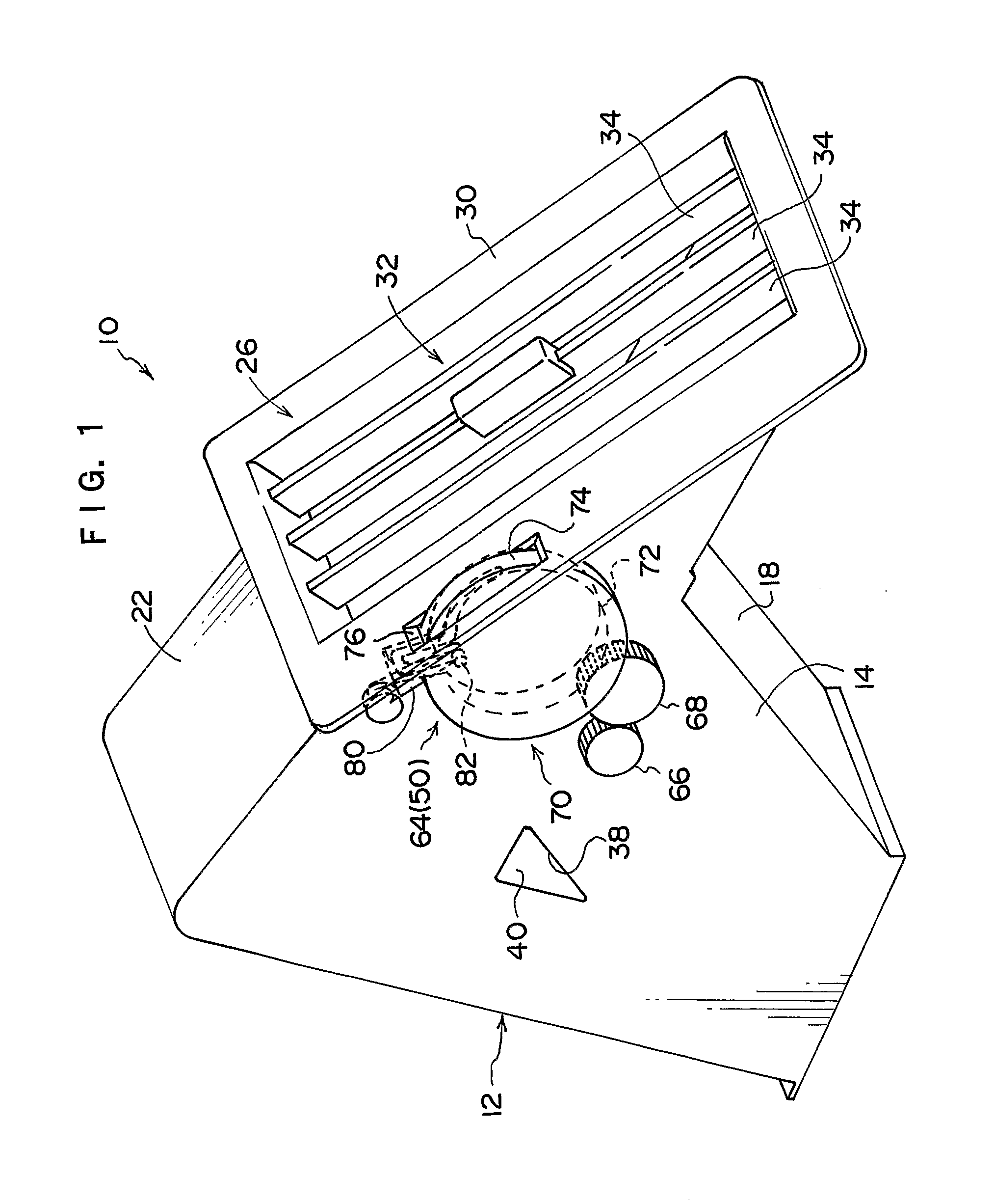
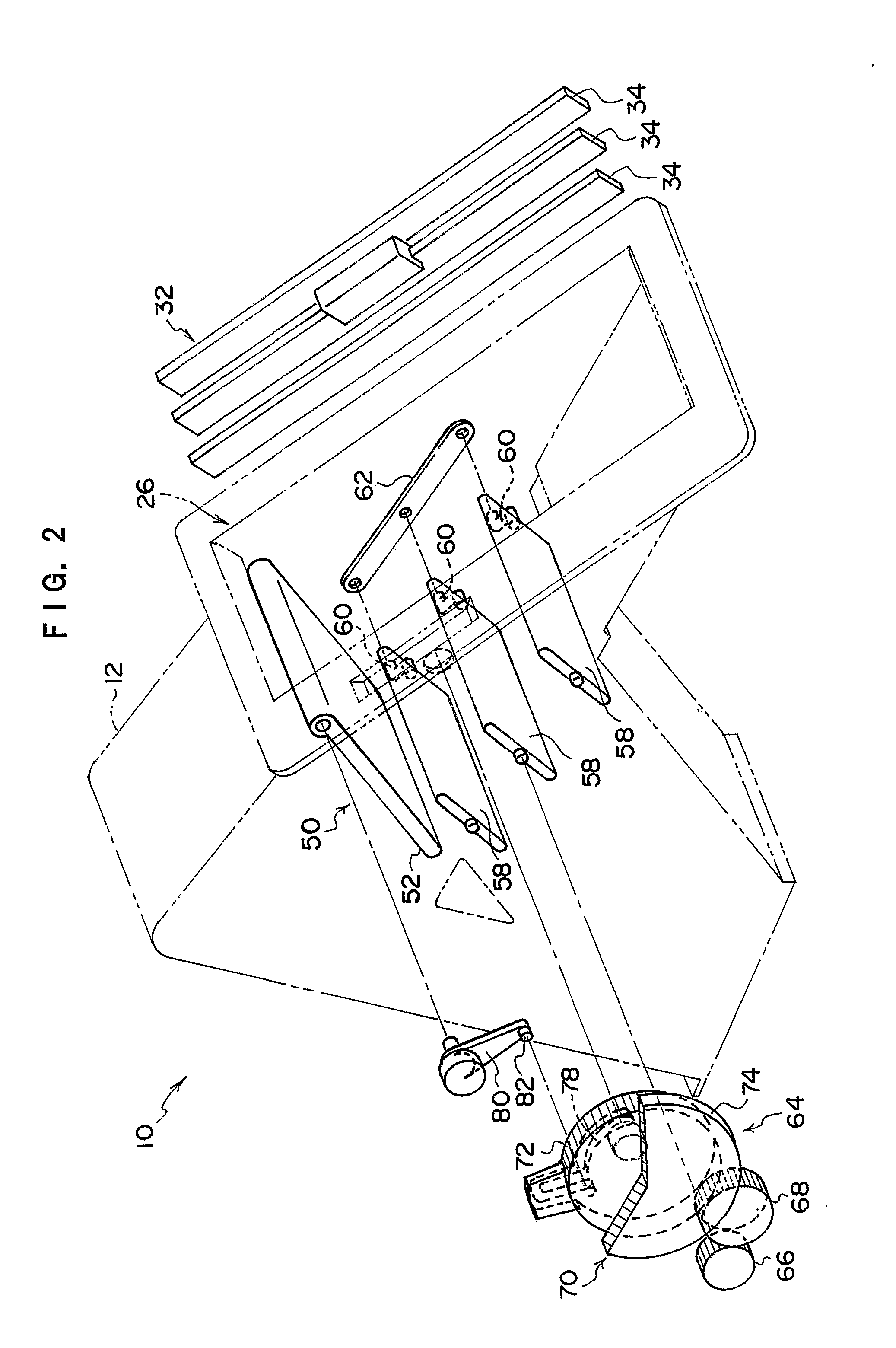
[0079]In the air conditioning register 10 relating to the present exemplary embodiment, when the operation dial 70 is operated and rotated in one direction around the axis thereof, interlockingly with the rotation of the operation dial 70, the first damper 52 rotates, and the longitudinal direction other end portion of the first damper 52 approaches the top wall 22. Further, when the operation dial 70 is rotated in this way, the second dampers 58 rotate interlockingly therewith. As shown in FIG. 3, when the first damper 52 rotates to being accommodated in the accommodating portion 54, the short-side directions of the respective second dampers 58 are as close as possible to the direction from the distal end portion of the abutting piece 56 to the top end portion of the inclined wall 18.

[0080]In this state, as described above, the adjacent second dampers 58 overlap one...

second exemplary embodiment

Operation of Second Exemplary Embodiment

[0104]The operation and effects of the present exemplary embodiment will be described next.

[0105]In the air conditioning register 90 relating to the present exemplary embodiment, when the operation dial 118 is operated and rotated around its axis, interlockingly with the rotation of the operation dial 118, the gear 134 rotates, and the shutter 102 moves forward or rearward. Therefore, when the operation dial 118 is operated and rotated as greatly as possible in one direction around the axis thereof, as shown in FIG. 7, the majority of or all of the shutter 102 is accommodated at the lower side of the top wall 106. On the other hand, when the operation dial 118 is operated and rotated as greatly as possible in the other direction around the axis thereof, as shown in FIG. 9, the majority of or all of the shutter 102 is pulled-out from the top wall 106.

[0106]When the operation dial 118 is operated and rotated in the one direction around the axis ...

third exemplary embodiment

[0117]A modified example of the second exemplary embodiment will be described next as a third exemplary embodiment.

[0118]The structure of main portions of an air conditioning register 147 relating to the present exemplary embodiment is shown in a perspective view in FIG. 11. The structure of the main portions of the air conditioning register 147 is shown in a cross-sectional view in FIG. 12. Note that the main portions of the air conditioning register 147 shown in FIG. 11 and FIG. 12 are portions of the extended wall 98 and the rear wall portion 110D of the peripheral wall 110 of the air conditioning register 90 of the above-described second exemplary embodiment. At regions other than the regions where the structures differ from the air conditioning register 90, the structures are the same as the air conditioning register 90.

[0119]As shown in FIG. 7, at the air conditioning register 90 relating to the above-described second exemplary embodiment, the outer diameters of the shaft port...


PUM


Abstract

There is provided an air conditioning register which can prevent or effectively suppress a reduction in an effective opening surface area at an air-conditioned air blow-out portion, and which has good blow-out efficiency of air-conditioned air. A first flow path 42 and a second flow path 44, whose directions toward a blow-out bezel 26 differ, are formed within a retainer 12 of an air conditioning register 10. A first damper 52 and plural second dampers 58, which are interlocked with one another, are provided at the retainer 12. The first damper 52 opens and closes the first flow path 42, and the second dampers 58 open and close the second flow path 44. The first damper 52 and the second dampers 58 are operated such that either one of the first flow path 42 and the second flow path 44 is opened and the other is closed, and the flow path of the air-conditioned air is switched. In this way, a blow-out direction of the air-conditioned air from the blow-out bezel 26 is controlled, while a reduction in an effective opening surface area at the blow-out bezel 26 is prevented or effectively suppressed.

Description

FIELD OF THE INVENTION [0001]The present invention relates to an air conditioning register which structures an air conditioner of a vehicle.DESCRIPTION OF THE RELATED ART [0002]As disclosed in Japanese Patent Application Laid-Open (JP-A) No. 2005-306224, an air conditioning register, which blows-out, into a vehicle cabin, air-conditioned air which has been generated at the main body of an air conditioner, has a retainer. The retainer structures the main body of the air conditioning register. The air-conditioned air, which has passed through the inner side of the air conditioning register, is blown-out to the interior of the vehicle cabin from a blow-out port which is provided at the retainer.[0003]Plural horizontal fins and plural vertical fins are provided at the blow-out port of the air conditioning register. The horizontal fins are narrow plate-shaped members whose longitudinal direction runs along the substantially transverse direction of the vehicle. The longitudinal direction ...

Claims


Application Information

Patent Timeline
Patent Type & Authority Applications(United States)
IPC IPC(8): F25D17/04
CPCB60H1/3421B60H2001/3478B60H2001/3464B60H1/12B60H1/34
Inventor SAKAKIBARA, KIMIONONOYAMA, MICHIYOTANAKA, KEIKOINOUE, MAKOTO
Owner TOYOTA JIDOSHA KK
Why Eureka
Try Eureka