Mechanical delay timer

a delay timer and mechanical technology, applied in the field of mechanical delay timers, can solve the problems of not being able to control the operation of either a toggle switch or a rocker switch, and cannot be used for control of a conventional wall switch,

Inactive Publication Date: 2010-10-21
HEIEN TROY A
View PDF17 Cites 1 Cited by
  • Summary
  • Abstract
  • Description
  • Claims
  • Application Information

AI Technical Summary

Benefits of technology

[0010]The delay timer of this invention is arranged to be installed over an existing or prior installed switch to change the switch position of either a toggle or a rocker type wall switch after a preset interval or to allow normal operation of the switch. The delay timer includes a spring driven timer means that rotates a cam plate which, in turn, imparts movement to an actuator through a cam follower which is attached to or is part of the actuator. The timer means, cam plate, and actuator are mounted within a housing which attaches to a timer base plate that fits over an existing switch cover plate without modification or disassembly of the switch. Movement of the actuator causes the toggle lever of a toggle switch to change position and also imparts a sliding motion to a pair of rails formed as extensions to the actuator and positioned to interact with the rocker member of a conventional rocker-type wall switch to cause the switch position to change from its “on” position to its “off” position.

Problems solved by technology

A drawback to such devices is that they cannot be used for control of a prior installed conventional wall switch.
None have the capability of controlling the operation of either a rocker switch or a toggle switch or both.

Method used


Image

  • Mechanical delay timer
  • Mechanical delay timer
  • Mechanical delay timer

Examples


Embodiment Construction

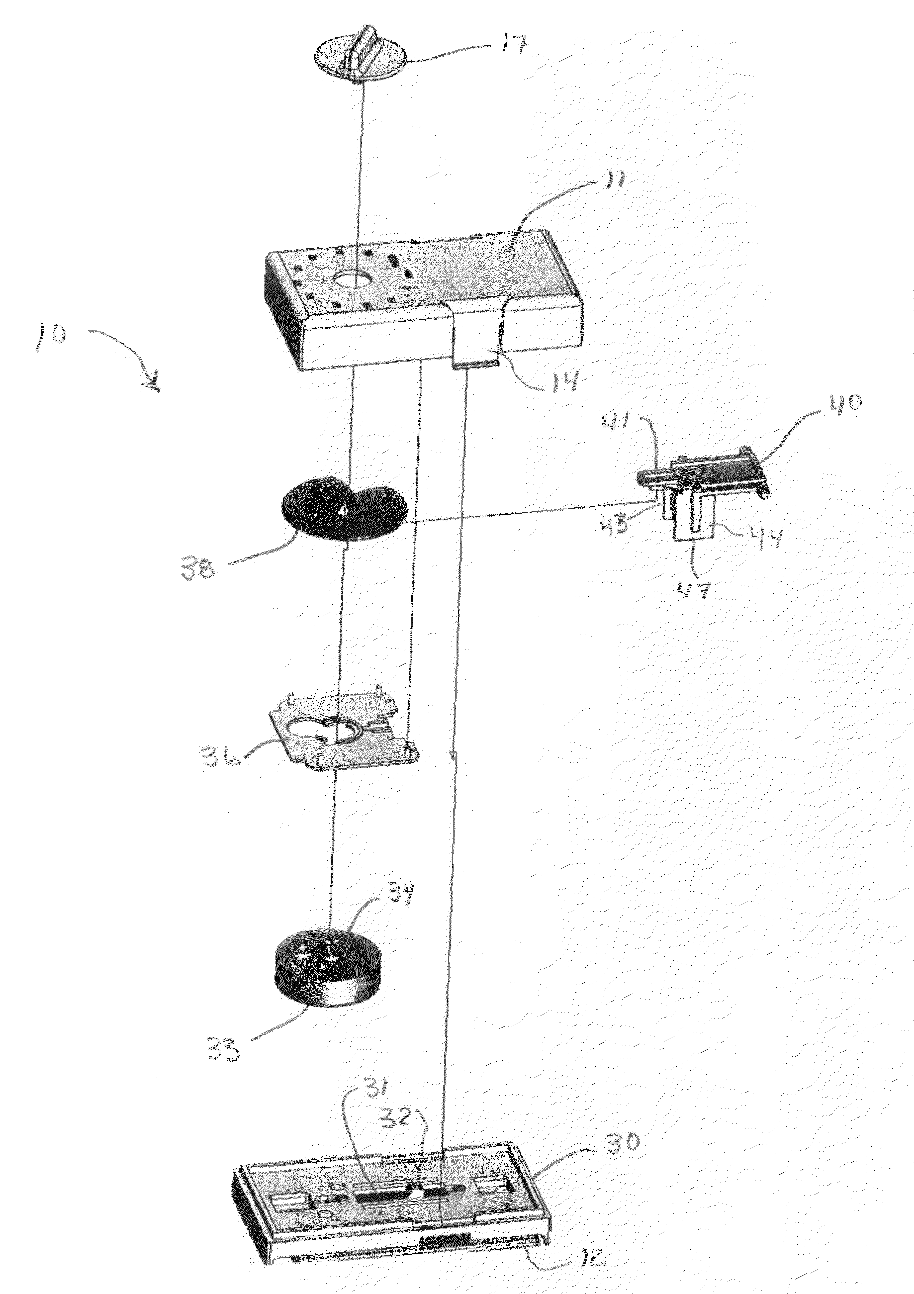
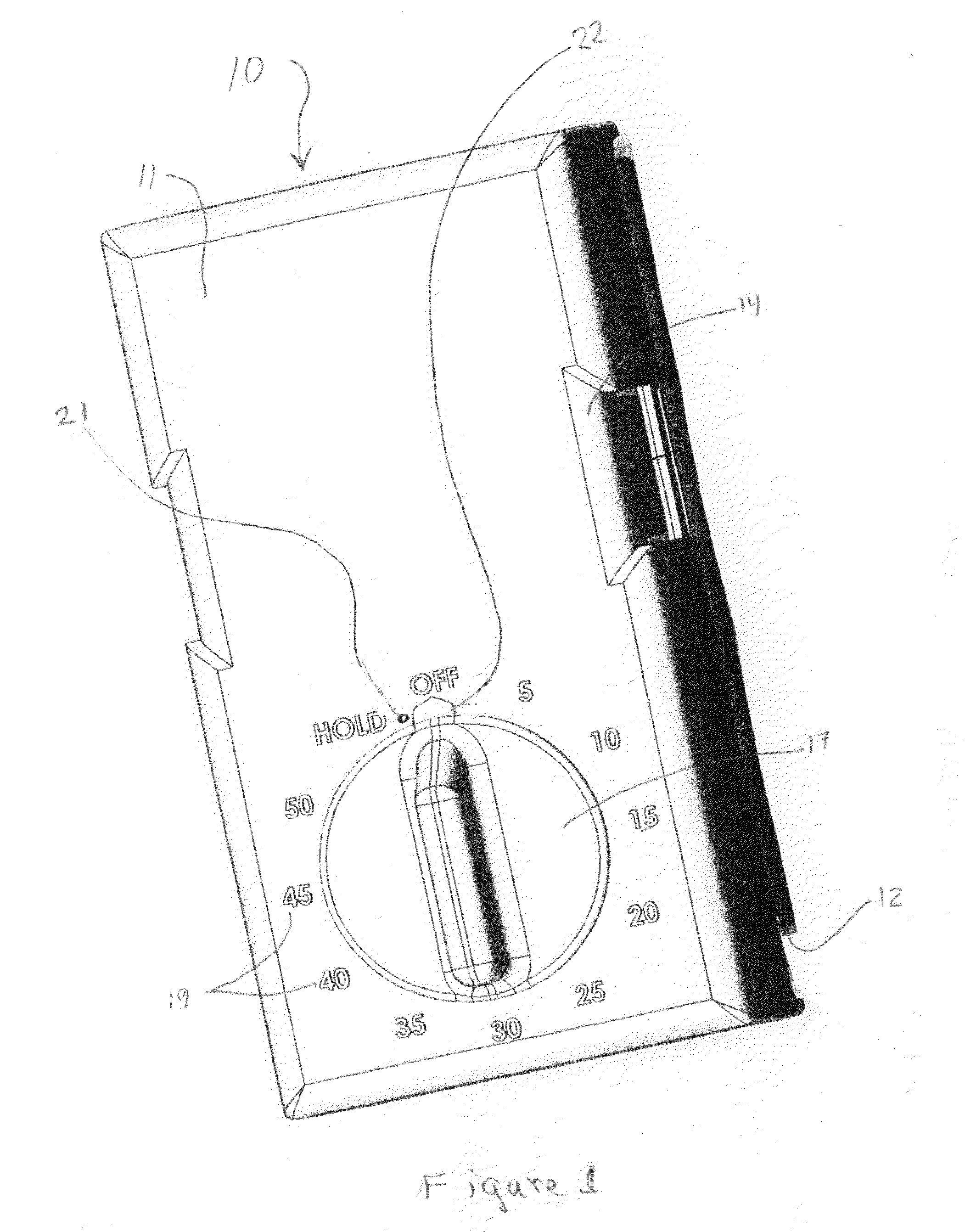
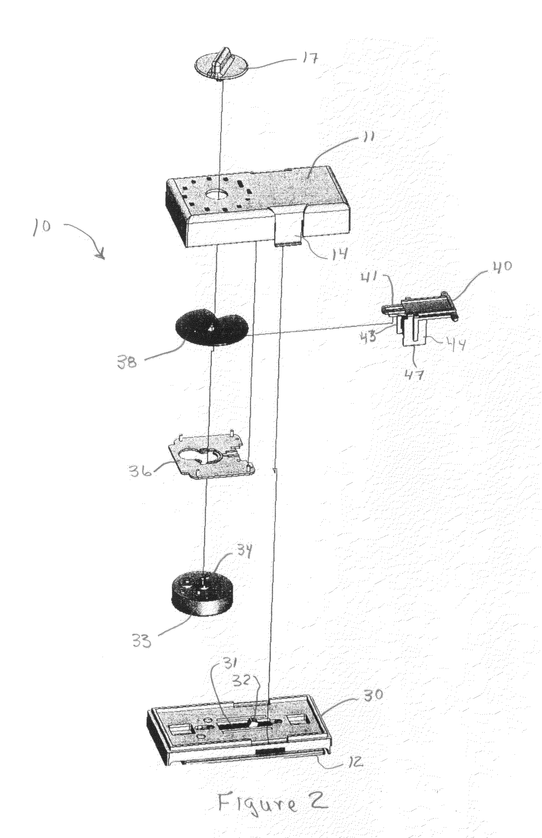
[0017]FIG. 1 shows the delay timer 10 as it would appear mounted over the cover plate of a conventional toggle or rocker wall switch. Timer 10 includes a timer housing 11 that fits over the cover plate 12 of a conventional toggle switch having a protruding lever or handle, or over the cover plate of a rocker switch in which one side of the switch is raised and the other side is depressed. The housing locks to a timer base (not shown in this view) by means of tab locks 14 and 15. A rotatable control knob 17 for setting the time delay for switch operation is located adjacent the bottom of the timer housing and is encircled by a time scale19 that may be calibrated in minutes. The time delay for switch operation is set by clockwise rotation of the control knob to the chosen setting. A small counter-clockwise rotation, from the “off” position to the “hold” position, does not engage the timer, but turns the switch on until the control knob is again turned. A removable stop such as a threa...


PUM


Abstract

A mechanical delay timer for operating either a toggle or a rocker-type wall switch to change the position of the switch after a preset interval includes a spring powered timer that drives a cam which, in turn, causes movement of an actuator that is arranged to engage either the toggle lever of a toggle wall switch or the rocker member of a rocker-type wall switch to move the switch from one position to another. The timer mechanism is contained within a housing that attaches to a timer base which, in turn, mounts over the existing cover plate of a conventional wall switch.

Description

BACKGROUND OF THE INVENTION[0001]1. Technical Field[0002]This invention relates generally to a mechanical delay timer that is arranged to turn a light switch or other electric switch on or off after a pre-set interval.[0003]More specifically, this invention relates to a mechanical delay timer that operates the existing switch mechanism of either a toggle or a rocker switch to allow the switch to be turned on and to then turn the switch off after a pre-set interval.[0004]2. Description of Related Art[0005]There are numerous devices for controlling individual lights and appliances to turn them on or off at pre-set times. Those devices typically are electromechanical in operation and may employ a small electric motor to change the position of a switch in series with the light or controlled appliance. That arrangement requires a power source which usually is a connection to the same source as supplies the light or appliance or both. A drawback to such devices is that they cannot be used...

Claims


Application Information

Patent Timeline
Patent Type & Authority Applications(United States)
IPC IPC(8): H01H43/10
CPCH01H7/08H01H43/127H01H43/04H01H23/14
Inventor HEIEN, TROY A.
Owner HEIEN TROY A
Why Eureka
Try Eureka