Management and Control Method of a Pressurization System

a technology of pressurization system and control method, which is applied in the direction of volume/mass flow by differential pressure, direct mass flowmeter, indirect mass flowmeter, etc., can solve the problems of achieving the desired effect, correspondingly high energy consumption, and most prone to damage for a continuous start-stop operation

Active Publication Date: 2020-12-24
CALPEDA
View PDF0 Cites 0 Cited by
  • Summary
  • Abstract
  • Description
  • Claims
  • Application Information

AI Technical Summary

Benefits of technology

[0017]The solution idea underlying the present invention is to provide a method that allows determining and optimizing the operating status of a pressurization system by an estimation of the flow rate starting from a minimum number of measured quantities.

Problems solved by technology

If the inlet pressure of the auxiliary pumps drops to a value that does not allow this lower limit value to be reached, the pressure-increase devices continue to operate unlimitedly at the maximum pump power, resulting in a correspondingly high energy consumption, pump wear and heating of the delivered medium, without at the same time obtaining the desired effect as regards the pressure level.
In particular, the component that is most prone to damage for a continuous start-stop operation, particularly in pumps operated with an asynchronous motor, is the condenser.
However, this expedient is often not enough.
Although advantageous and alternative to the use of expensive flow rate sensors, the currently known methods provide for the adoption of a plurality of measuring tools, with greater complexity and cost of the overall system.
Furthermore, the adoption of a plurality of measuring systems may lead to different possible measurement errors, which may be combined and amplified in the overall estimation of the flow rate.

Method used


Image

  • Management and Control Method of a Pressurization System
  • Management and Control Method of a Pressurization System
  • Management and Control Method of a Pressurization System

Examples


Embodiment Construction

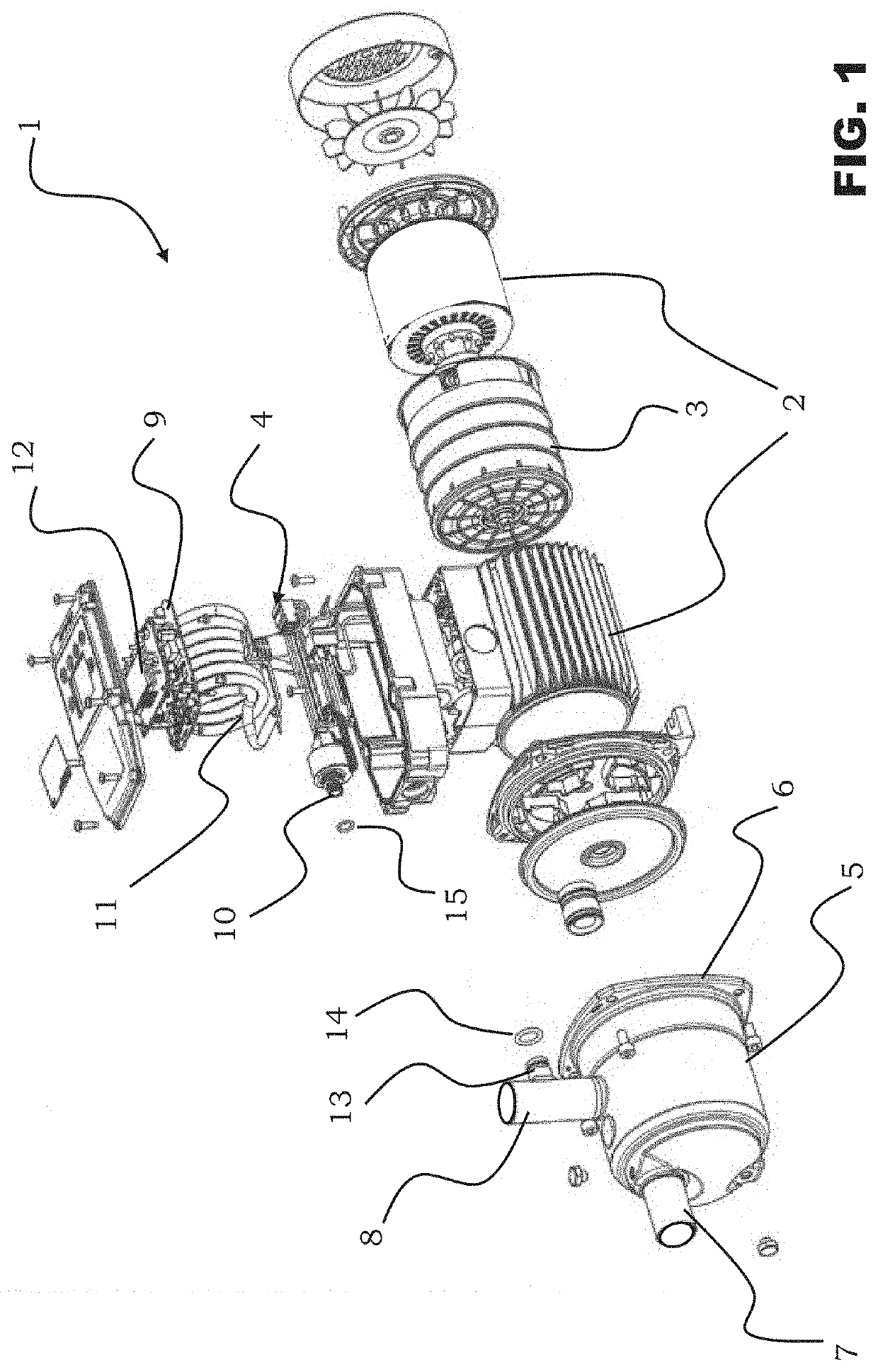
[0048]With reference to the figures, reference number 1 globally and schematically indicates a pressurization system made according to the present invention.

[0049]The pressurization system 1 comprises an electric motor 2, a hydraulic unit 3 and a control electronic unit 4.

[0050]Electric motor 2 and hydraulic unit 3 are kinematically coupled by means of a motor shaft.

[0051]The electric motor 2 is preferably of the two-phase asynchronous type.

[0052]The hydraulic unit 3 is received into a volute 5, through an open side 6 of the volute 5.

[0053]From the volute 5 a liquid suction duct 7 and a liquid delivery duct 8 depart, which are internally threaded for coupling with the supply and distribution pipes (not shown) of the hydraulic system on which the pressurization system 1 of the present invention is inserted.

[0054]The electric motor 2, in the exemplifying embodiment of FIG. 1, is laterally coupled to the control electronic unit 4. The control electronic unit 4 comprises a control elect...


PUM


Abstract

A management and control method for at least one operation parameter of a pressurization system operated by an electric motor, the method comprising the steps of: detection of an operating pressure value at a delivery duct of the pressurization system, by means of a single pressure sensor; estimation of a hydraulic flow rate and a hydraulic head by means of an algorithm which is implemented in a control software based on the operating pressure value detected by means of the single pressure sensor; estimation of a motor rotation speed of the pressurization system based on the operating pressure value and on the number of blades of the impeller of said pressurization system as a result of said estimation; and processing of an on/off signal of the pressurization system. Also disclosed is a pressurization system, comprising a pressure value and a control electronic unit adapted to perform said method.

Description

CROSS-REFERENCE TO RELATED APPLICATION[0001]This application claims priority to Italian Patent Application No. 102019000009747, filed Jun. 21, 2019, which is hereby incorporated by reference herein in its entirety.BACKGROUND OF THE INVENTIONField of Application[0002]The present invention relates to a management and control method for at least one operation parameter of a pressurization system, operated by means of an electric motor.[0003]The above method finds useful application in particular, but not exclusively, in the field of pumps and of pressurization units equipped with fixed or variable-speed electric motors, in particular the electric motors of the asynchronous type.Prior Art[0004]It is known, in the present field, that in water supply networks where the network pressure is not sufficient or sufficiently stable to supply water to consumers who are at a high level, pressure-increase devices, commonly known as “booster pumps”, are adopted. Generally, at least one main pressur...

Claims


Application Information

Patent Timeline
Patent Type & Authority Applications(United States)
IPC IPC(8): F04D15/00F04D13/06
CPCF04D13/06F04D15/0066G01F1/34G01F1/88G01F1/80F04D15/0094F04D15/0218F05D2260/81F05D2270/3013G01P3/263
Inventor BARONCINI, TIZIANAMARANGON, GIANLUCAMARCHETTI, ALBERTOMENARA, IVAN
Owner CALPEDA
Why Eureka
Try Eureka