Color printer toner transfer belt system and process

Inactive Publication Date: 2009-01-15
CLOVER TECH GROUP
View PDF6 Cites 0 Cited by
  • Summary
  • Abstract
  • Description
  • Claims
  • Application Information

AI Technical Summary

Benefits of technology

[0013]It is also an object of the present invention that a method for resetting the counter on the transfer belt assembly can be reset or rep

Problems solved by technology

In some models, though there is no option to reset the printer and failing to replace the unit will end-up in inability to print.
Failure to replace the transfer unit for a long period of time might cause poo

Method used


Image

  • Color printer toner transfer belt system and process
  • Color printer toner transfer belt system and process
  • Color printer toner transfer belt system and process

Examples


Embodiment Construction

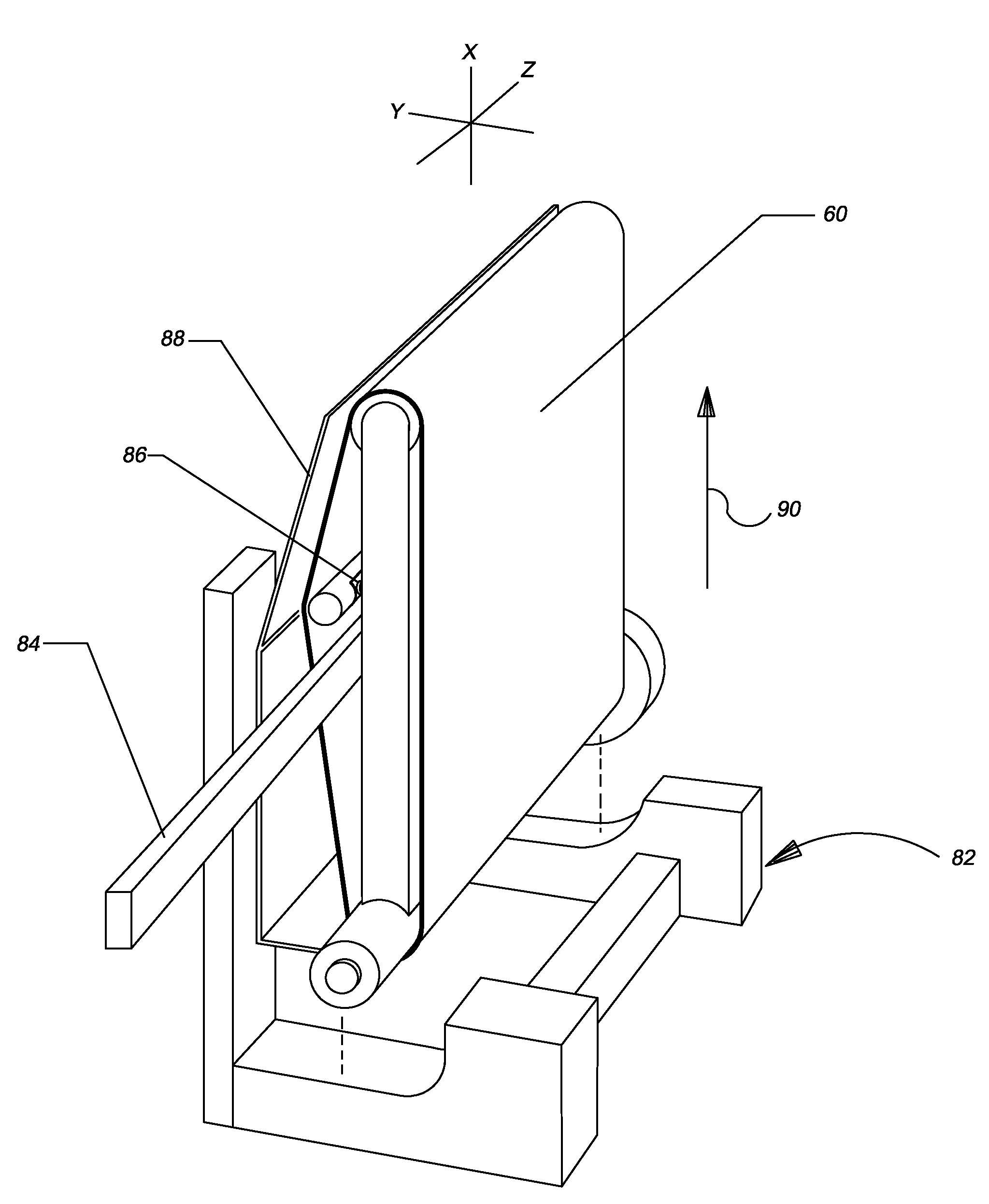
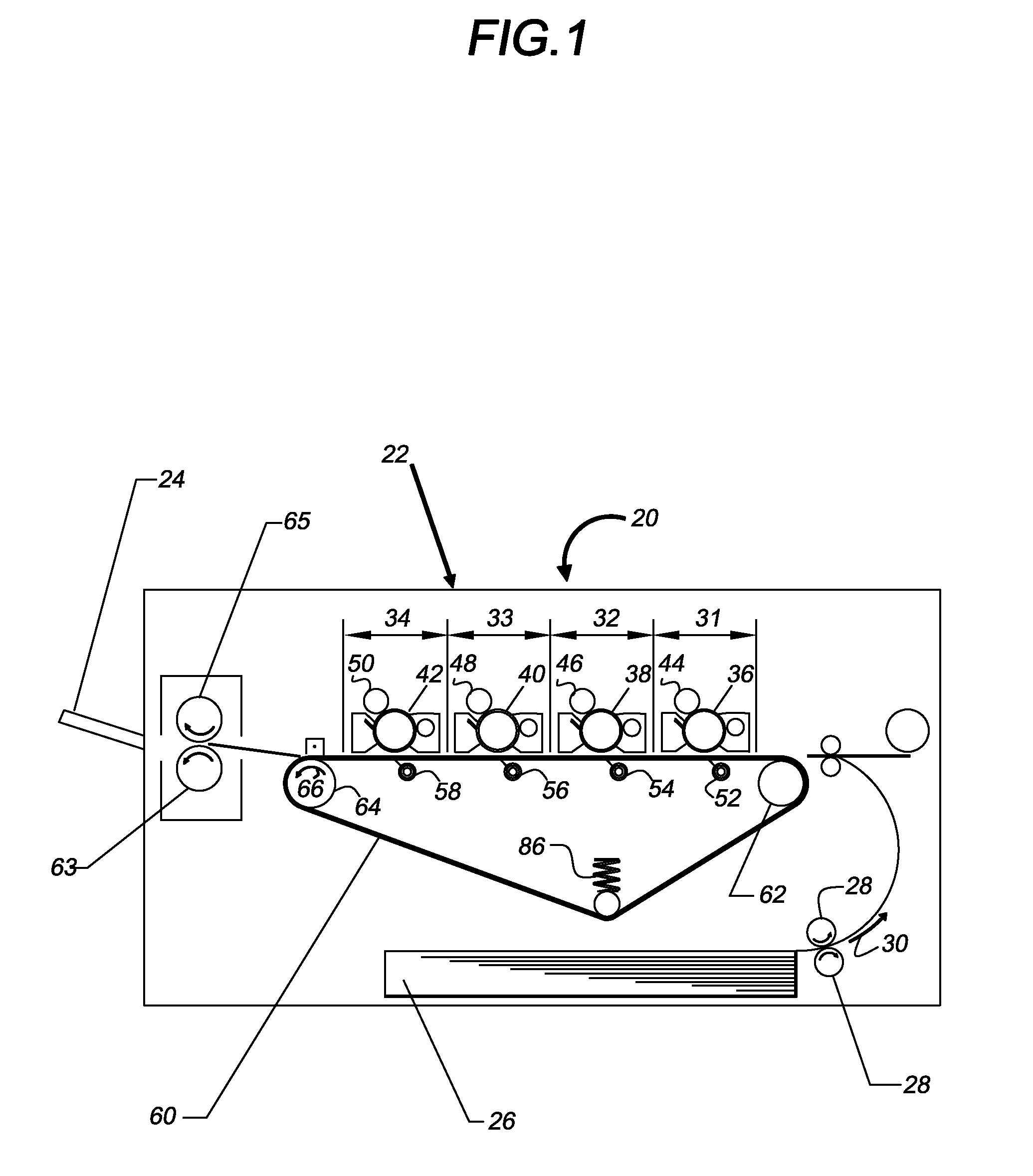
[0020]Referring to FIG. 1 a cross-sectional, schematic view of a color laser printer, image-forming apparatus 20 is shown. Also, for convenience the major components of the printer will be described with reference to an x-y-z axis Cartesian coordinate system. Details of the construction and operation of a printer of the type shown in FIG. I may be found in the '893 patent. The printer 20 includes a housing 22 and a media exit shelf 24. Typically the media is paper and shelf or tray 24 is referred to as the paper exit shelf or tray 24. The printer also includes an internal paper feed tray 26 that generally lie in an x-z plane, with the x directions going from left to right, and the z directions going into and out of the page as shown in FIG. 1. The y directions go from bottom to top in FIG. 1. Pick-up rollers 28, 28 are shown with the paper feed in the direction of arrow 30. The axes of rotation of the rollers 28, 28 extend into the page of FIG. 1 in the z direction.

[0021]The printer...


PUM


Abstract

A system and method to replace a transfer belt of a color laser printer transfer belt assembly without replacing the entire assembly, including one or more novel holding fixtures and a method for releasing the tension on the transfer belt prior to removal of the transfer belt from the assembly, then reapplying tension to a replacement transfer belt and, optionally, replacing the motor assembly and/or the microchip that controls operation of the transfer belt assembly.

Description

FIELD OF INVENTION[0001]The invention relates generally to the field of laser toner printers, and more specifically to repair and remanufacture color laser toner printer transfer belt assemblies.BACKGROUND OF INVENTION[0002]In recent years a plural color or full color image forming apparatus of the electro-photographic type, for example, laser color printers, there has been put into practical use a so-called in-line type image forming apparatus in which a plurality of photo-sensitive drums are arranged in a plane in conformity with respective colors arranged sequentially. Toner images of the respective colors are formed on respective photosensitive drums are successively super-imposed on a media, typically paper that is positioned on a transfer belt to thereby form a color image as the transfer belt and the media are advanced in a forward direction in the plane. The transfer belt is positioned around a plurality of rollers, each roller having its axis of rotation perpendicular to th...

Claims


Application Information

Patent Timeline
IPC IPC(8): G03G15/01
CPCG03G15/167G03G15/0194G03G2221/1642G03G2215/1623
Inventor WAZANA, YOELSHANUN, SAGIE
Owner CLOVER TECH GROUP
Why Eureka
Try Eureka