Methods and apparatuses for clamping a jet pump sensing line support

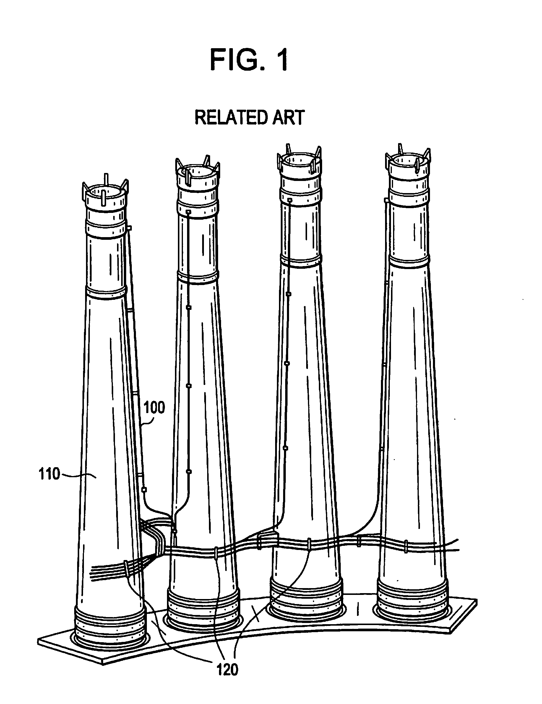
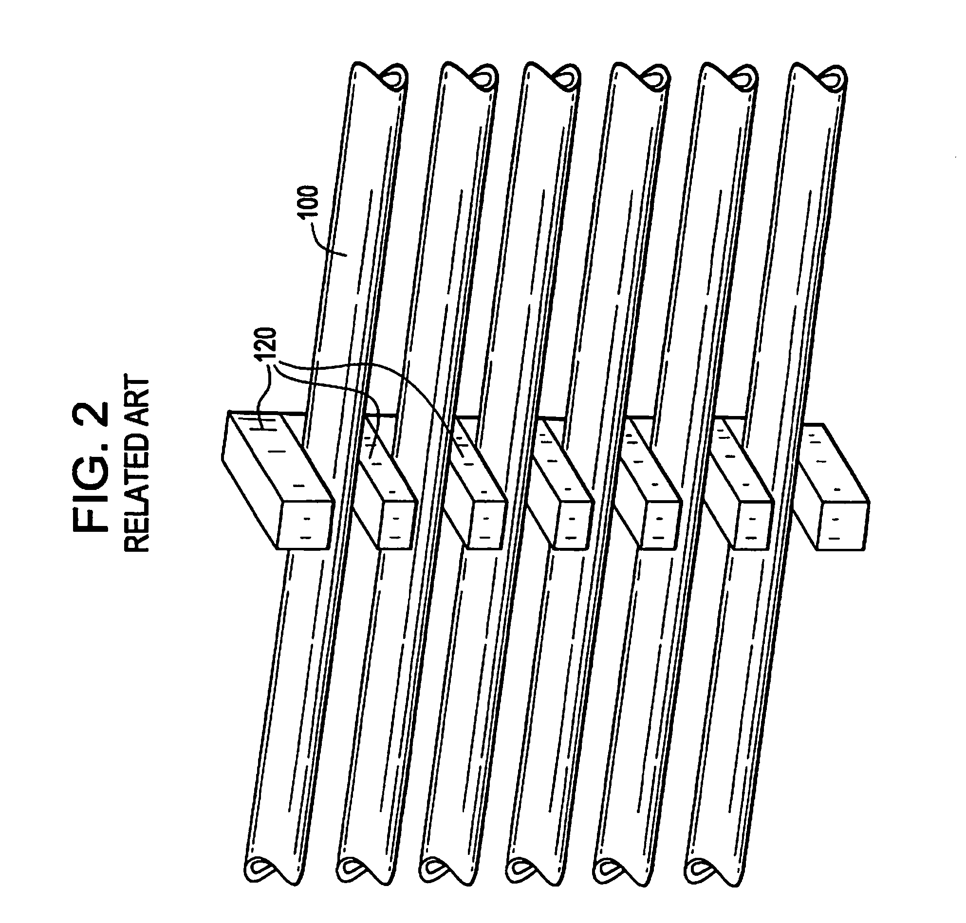
a technology of sensing line support and jet pump, which is applied in the field of jet pump sensing line support clamping apparatus, can solve the problems of high vibration and radioactivity, components within the core, including jet pump sensing line b>100/b> and sensing line supports b>120/b>, may be subject to premature damage,

Inactive Publication Date: 2010-10-21
GE HITACHI NUCLEAR ENERGY AMERICAS
View PDF4 Cites 11 Cited by
  • Summary
  • Abstract
  • Description
  • Claims
  • Application Information

AI Technical Summary

Problems solved by technology

BWR core operating conditions may include high levels of vibration and radioactivity.
Components within the core, including jet pump sen

Method used


Image

  • Methods and apparatuses for clamping a jet pump sensing line support
  • Methods and apparatuses for clamping a jet pump sensing line support
  • Methods and apparatuses for clamping a jet pump sensing line support

Examples


example embodiment

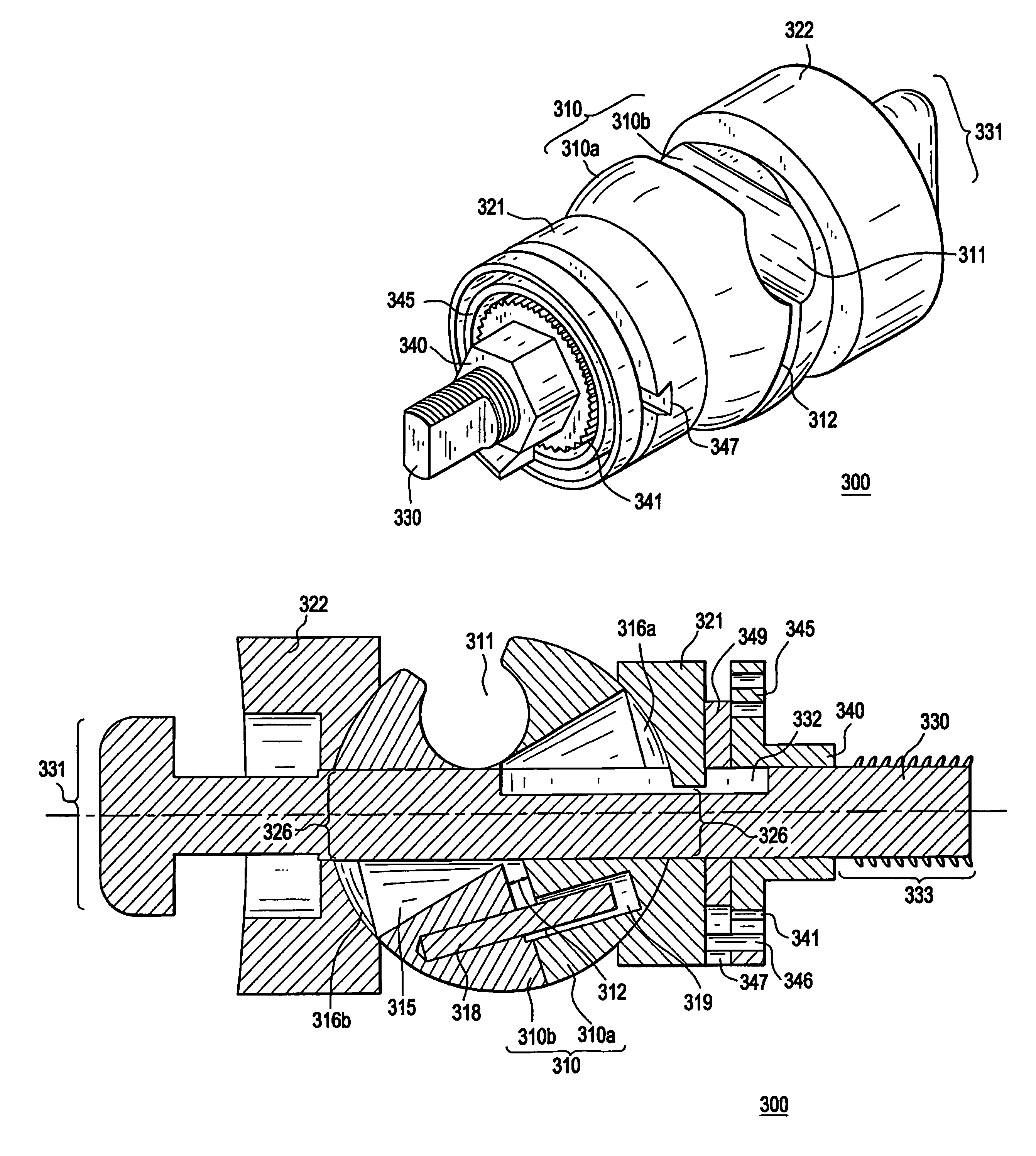
[0030 clamp further includes a clamp post 330 that extends axially through various components discussed above, including ball subassembly 310 and clamp jaws 321 and 322. Clamp post 330 may align and hold clamp components through which it passes. Clamp post 330 may include a T-shaped attaching end 331 that is shaped to pass through a slot in a component to be clamped to and lock in the slot in the component so as to not be able to be withdrawn back through the slot, when turned 90-degrees, as discussed below with regard to example methods. Other shapes and attachment configurations and mechanisms are possible for attaching end 331 while still securing example embodiment clamps to desired components. Clamp post 330 may include a recessed area 332 in which a portion of jaw clamp 321 may be seated, in order to restrict the range of motion of jaw clamp 321 along clamp post 330. Alternate recesses and / or stops may be placed on clamp post 330 in order to control and / or restrict the motion ...


PUM


Abstract

Example embodiment clamps may be used to clamp two components together, with a degree of freedom of motion between the clamped components, including both rotational and translational motion. Example embodiment clamps may clamp a BWR jet pump sensing line to a diffuser as a repair or installation of a sensing line support. Example clamps may include a ball subassembly that holds a component and allows rotation and twisting of the component within the clamp. Example clamps may further include jaws holding the ball subassembly and a biasing element that permits tightening of the clamp.

Description

BACKGROUND[0001]1. Field[0002]Example embodiments and methods generally relate to nuclear power plant components, specifically, jet pump sensing line support clamp apparatuses.[0003]2. Description of Related Art[0004]Generally, Boiling Water Reactors (BWRs) include jet pumps as part of a recirculation system to effectively move coolant and moderator through a nuclear core. In order to evaluate operating conditions within the nuclear core, it may be desirable to monitor flow rate through the core, including flow rate of coolant from the jet pumps. Typically, a jet pump sensing line is used to measure flow rate from the jet pumps by measuring a pressure differential in the jet pumps.[0005]FIGS. 1 and 2 are illustrations of related art jet pump sensing lines 100 coupled to a lower diffuser shell 110 at the base of the jet pumps by sensing line supports 120 welded to both the diffuser shell 110 and the jet pump sensing lines 100. The sensing lines 100 are conventionally welded to the su...

Claims


Application Information

Patent Timeline
IPC IPC(8): G21C15/25F16L3/015
CPCY02E30/31G21C15/25Y02E30/30
Inventor MATSUMOTO, JACK TOSHIO
Owner GE HITACHI NUCLEAR ENERGY AMERICAS
Why Eureka
Try Eureka