Method and apparatus for door selectable automatic unlocking sensor

Inactive Publication Date: 2010-10-21
HONDA MOTOR CO LTD
View PDF22 Cites 12 Cited by
  • Summary
  • Abstract
  • Description
  • Claims
  • Application Information

AI Technical Summary

Benefits of technology

[0010]One advantage of this invention is that a user can individually set which passenger doors are unlocked when the transmission is shi

Problems solved by technology

While known door lock system logic generally works well for its intended purpose, there are known limitations.
One limitation is that additional passenger door lock/unlock options may be desirable.
Another limitation is that the understanding r

Method used


Image

  • Method and apparatus for door selectable automatic unlocking sensor
  • Method and apparatus for door selectable automatic unlocking sensor
  • Method and apparatus for door selectable automatic unlocking sensor

Examples


Embodiment Construction

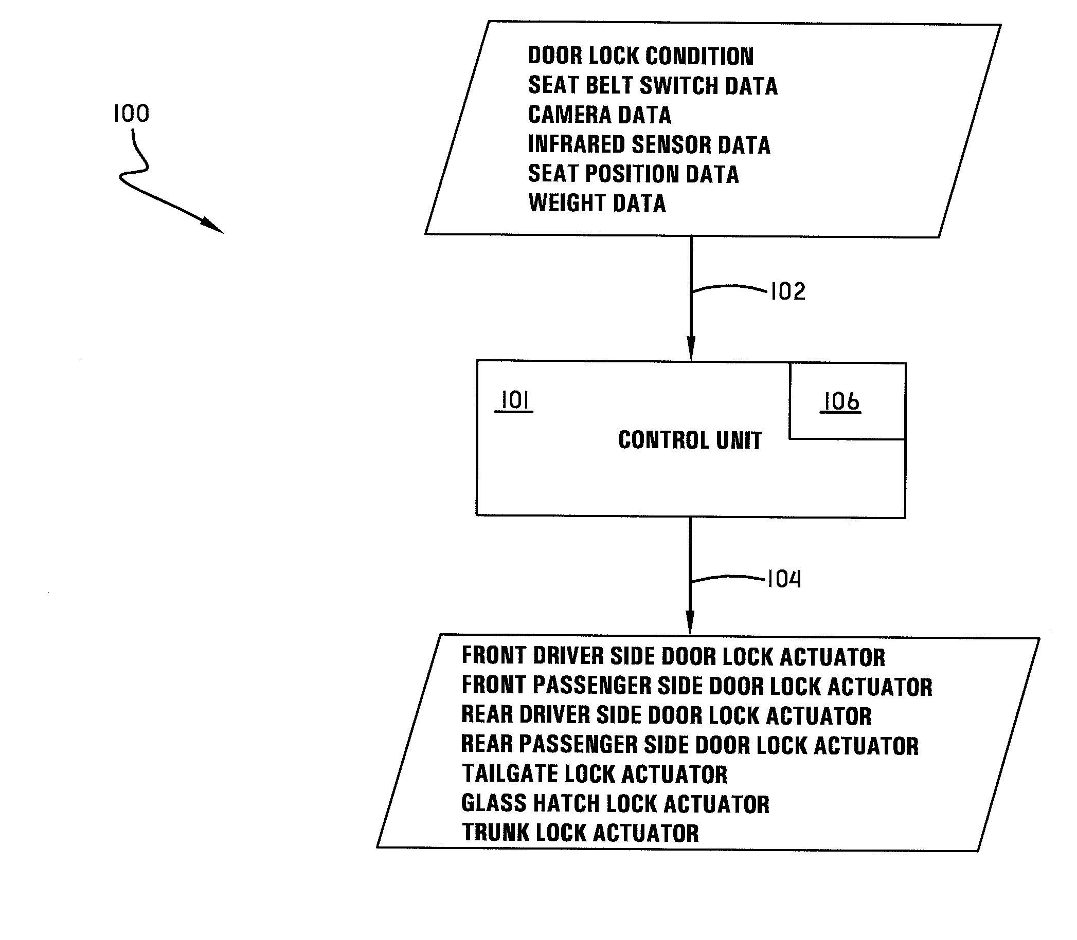
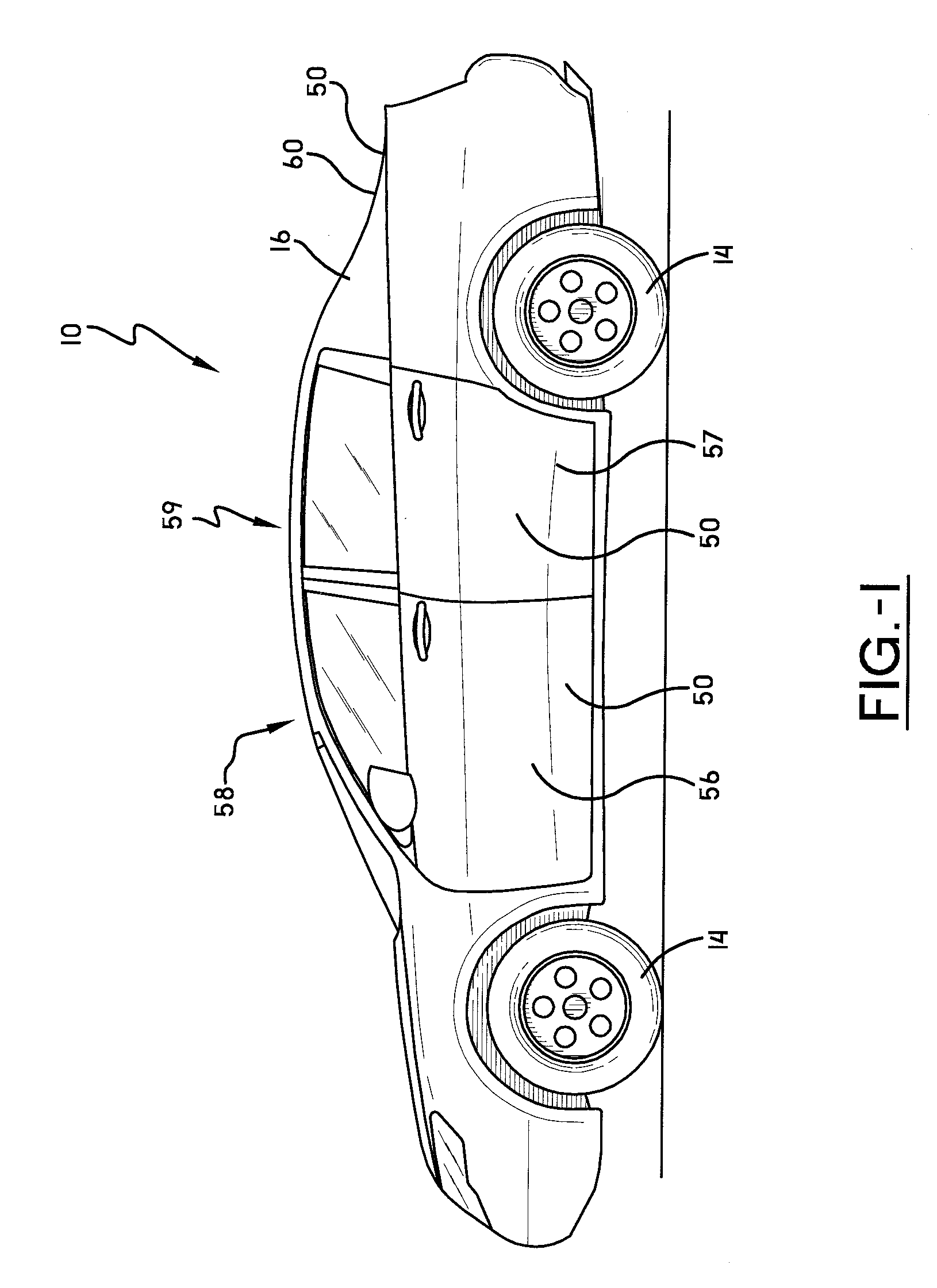
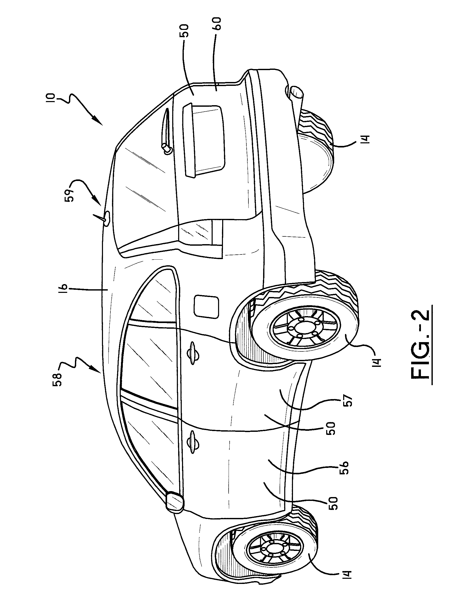
[0026]Referring now to the drawings wherein the showings are for purposes of illustrating embodiments of the invention only and not for purposes of limiting the same, and wherein like reference numerals are understood to refer to like components, FIGS. 1-3 show a vehicle 10 that may be equipped with a door lock system 100 according to one embodiment of this invention. While the vehicle 10 shown in FIG. 1 is a sedan, and the vehicle shown in FIG. 2 is a sports utility vehicle (SUV), it is to be understood that the door lock system 100 of this invention will work with any vehicle including, for some non-limiting examples, cars, vans, trucks, airplanes, and boats. The vehicle 10 may include a frame 12, one or more ground engaging wheels 14 operatively mounted to the frame 12, a body 16 mounted to the frame 12, and a locomotion source 18 mounted to the frame 12 for use in providing locomotion for the vehicle 10. The locomotion source could be of any type chosen with the sound judgment o...


PUM


Abstract

A vehicle door lock system may include a control unit for selectively unlocking a door, the control unit having an input for receiving a signal from an occupant detection system, a logic unit for determining whether to send an unlock signal to the door based upon the input, and an output for selectively sending the unlock signal to the door when the automatic door unlock conditions are met.

Description

I. BACKGROUND OF THE INVENTION[0001]A. Field of Invention[0002]This invention pertains to the art of methods and apparatuses related to automatically locking and unlocking vehicle passenger doors and more specifically to methods and apparatus related to automatically locking and unlocking selected vehicle passenger doors.[0003]B. Description of the Related Art[0004]It is well known in the art to provide vehicle passenger doors with an automatic lock system. Current door lock system logic, for example, is used to lock the doors when the driver shifts the transmission out of park. When the driver shifts the transmission back into park, there are a few different known automatic door lock / unlock options: (1) one option unlocks the driver door only; (2) a second option unlocks all the passenger doors; and, (3) a third option does not adjust the locks of any passenger doors—they all remain locked.[0005]While known door lock system logic generally works well for its intended purpose, there...

Claims


Application Information

Patent Timeline
IPC IPC(8): G06F19/00G05B19/00
CPCE05B77/48B60N2/002
Inventor BINFET, MICHAELSGUEGLIA, JOHN
Owner HONDA MOTOR CO LTD
Why Eureka
Try Eureka